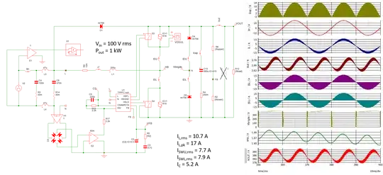
I have looked at the various stress on the components for a 1-kW output power when supplied by a 100-V rms input voltage. Each PFC delivers 380 V dc. The below picture shows a CCM boost operated in fixed frequency without input voltage sensing:
The stress on the components is given above the schematic and shows a peak inductor current of 18 A with a fairly high rms current in the output capacitor. As stated in the comment, the classical boost converter is the simplest implementation and I've seen many circuits driving two paralleled MOSFETs and a SiC diode for a 1-kW power. Fairly straightforward operation. There are plenty of controllers for this application. A good overview on PFC operation is given here.
If we now go for a totem-pole PFC, as the one illustrated below, you can choose the same predictive control technique without input voltage sensing but the control of the power switches becomes seriously more complicated. You can have a look at the seminar I recently released on PFCs. This is because each high-frequency switch changes role depending on the input line polarity. So input line sensing for this management is important and, in particular, the transitions near the 0-V region with soft-start for these switches (see this paper from TI):
As expected, the overall stress is similar to that of the classical boost. I have adopted here a slow leg made of diodes but synchronous rectification is obviously a must if you want the best efficiency. Many comments coming from power designers point the nightmare to pass EMI tests with this TPPFC structure (see here).
Finally, you can consider the interleaved version which requires two inductors but you will reduce the stress on the semiconductors and particularly on the output capacitor:
I have kept the same inductors for the sake of comparison but you can certainly reduce their value. The peak and rms currents for these passive elements is much smaller compared to the previous embodiment. The rms current on the output capacitor is linked to a reduced high-frequency ripple current (the low-frequency contributor remains the same) and it is significantly smaller than with the two other approaches.
As a preliminary conclusion, the simple boost circuit looks like the simplest option to choose with its good efficiency and the numerous controllers to choose from. For the best efficiency, the TPPFC is a possibility but there aren't many PWM controllers so far (TI and onsemi to name a few) and implementation can be challenge. The Barbi bridgeless PFC can be a viable alternative. Finally, the interleaved PFC brings the lowest stress on the semis and magnetics but may require a larger PCB area compared to the other circuits. Please note that the SIMPLIS models are parts of the free ready-made templates you can download from my page.


