1

I want to build a negative resistance converter and the only voltage source I have is a 5 V Arduino power pin.

I am afraid the reverse current (Is) flowing through the power pin will destroy my Arduino and render it useless for future projects.

Are my worries well founded or is the direction of the current flowing through the Arduino not important?

enter image description here

Circuit fantasist
  • 13,593
  • 1
  • 17
  • 48
  • 2
    A negative impedance converter will drive current into your voltage source. If that voltage source is an Arduino pin then current will flow into the Arduino pin. Keep the reverse current limited to the IO value stated in the data sheet. – Andy aka Mar 07 '23 at 18:47
  • What source is actually powering your op amp? What is the intended signal and context for this negative impedance converter? Why can't the 5V be derived from the same rails that are powering the op amp? The schematic shown uses an ideal op amp without any power pins shown but a real op amp is going to need to have its supply pins powered somehow. – nanofarad Mar 07 '23 at 18:48
  • @nanofarad I'd like to power it with the same arduino. – Reinhardt Walzer Mar 07 '23 at 18:50
  • 2
    So when you do the accounting for currents, *including* the supply current to keep the op amp fed, do you actually backfeed the Arduino supply? There's something fishy with KCL/conservation of charge here, and the simulation doesn't have good enough fidelity to make it clear. I also fail to see how you'd actually get the -5 mA observed when the op amp is powered by 5 V rails; as far as I can tell the op amp would just saturate. Unfortunately, I can't actually figure out what you are trying to do, because this isn't similar to any applications for negative impedance converters I've seen before. – nanofarad Mar 07 '23 at 18:51
  • I'm not really familiar with the term "backfeeding", but I could maybe use another arduino to power the opamp to avoid some issues. – Reinhardt Walzer Mar 07 '23 at 18:55
  • 2
    @ReinhardtWalzer The term "backfeeding" refers to your own claim that reverse current will be fed into your power pin. I am skeptical that an actual op amp, powered by some power pin, can produce a net reverse current back into that same pin, and your simulation completely neglects the current being used to power the op amp, by using an op amp model that is highly oversimplified and omits its power supply pins. While ideally I would try to run my own simulation with a fixed model, I'm a bit confused by your circuit and I cannot ensure that my attempt to do so would reflect your intent. – nanofarad Mar 07 '23 at 18:56
  • @nanofarad I'm only trying to emulate the circuit I found on this wikipedia page https://en.wikipedia.org/wiki/Negative_impedance_converter. I couldn't really find a clear physical implementation of the circuit on the internet. – Reinhardt Walzer Mar 07 '23 at 19:01
  • @ReinhardtWalzer It would make sense to emulate that circuit as a way of applying a (virtual) negative impedance to some net or circuit, but connecting it straight to a power supply is probably not going to lead to an expected or meaningful result. Consider simulating it first, with better op amp models and a separate supply voltage. At the moment, you're planning a build based on an analysis that is incomplete and overlooks key factors about how the op amp is powered. – nanofarad Mar 07 '23 at 19:16

2 Answers2

2

the only voltage source I have is a 5 V Arduino power pin.

In the comments you say that you also want to power the op amp from the Arduino's 5 V power pin. However in the simulation you are using an 'ideal' op amp with 'infinite' power supply voltages. This is why you are seeing a current being forced into the power pin.

For an accurate simulation you should use a real op amp (preferably the same or equivalent to the actual op amp you intend to use) powered from the Arduino 5 V supply. The output of this op amp will be constrained within the power rails of 0 V to 5 V, so it will not be able to push current into the power pin.

Bruce Abbott
  • 55,540
  • 1
  • 47
  • 89
2

Basic idea

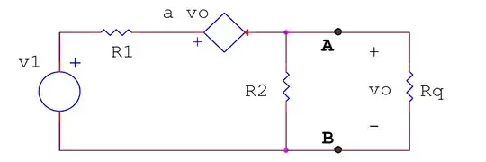
The idea of your circuit known as "current-inversion negative impedance converter" (INIC) is extremely simple. It is just a non-inverting amplifier with a gain of 2 and a resistor (voltage-to-current converter) connected between the circuit output and input.

Operation

The voltage across the resistor is 2.Vin - Vin = Vin; so the current through it (and injected back to the input voltage source) is Vin/R. This is the same amount of current that would be consumed from Vin if the latter was loaded with the same 1 k resistor... but its direction is reversed (instead of going out of the input voltage source it goes into it). It is as if the load current of the 1 k "positive" resistor is reversed and the circuit behaves like a 1 k negative resistor; hence the name of the circuit.

OP's problem

So in order for your circuit to work properly (op-amp not saturate), you need to supply the op-amp with twice the input voltage (10 V)... or reduce Vin twice at least. I recommend you reduce Vs (Arduino supply) with a voltage divider to 2 V.

Applications

This circuit makes some sense in the case if the op-amp was powered by an external source. Then, unlike the Arduino which consumes current from Vs, the circuit will add current and help Vs.

Famous applications of this negative resistance circuit are the Howland current source, Deboo integrator and "negative-resistance load canceller".

Building a load canceller

I will illustrate the idea of ​​this weird circuit through one of its exotic applications called "load canceller". For this purpose, I will build the circuit step by step and examine it using CircuitLab. To keep the schematics simple and clear, I have not used named nodes and ordinary DC simulation but live DC simulation. So hover your mouse over elements and their terminals to see the quantity values.

STEP 0: The problem. Imagine that, for some purpose, we have to reduce the voltage of a voltage source (Vin) by two times.

STEP 1: Voltage divider unloaded. To do it, we assemble a voltage divider by connecting two 10k resistors in series. Setting, for example, an initial input voltage Vin = 10 V, wee see an output voltage Vout = 5 V (exactly equal to the calculated).

schematic

simulate this circuit – Schematic created using CircuitLab

STEP 2: Voltage divider loaded. With the voltage thus obtained, we decide to supply some load RL = 1 k. Unfortunately, the load consumes current and the voltage drops (from 5 V to only 833 mV).

schematic

simulate this circuit

STEP 3: Voltage follower. The remedy is to supply current to the load not from the input voltage source but from some other additional source. The usual solution to do it is to connect a voltage follower between the divider's output and the load. It creates a "copy" of the divider's output voltage and supplies the load with it.

schematic

simulate this circuit

STEP 4: Conceptual INIC. But there is another more extravagant solution - to directly supply the current to the load by means of this type of negative resistor. To produce current, we need a voltage source and a resistor in series. Figuratively speaking, since the load RL "pulls down" the output, we connect another resistor R3 = RL that "pulls up" the output. Note that a "humble" constant voltage source does not work for us, it must be a proportional (dynamic) voltage source. To immitate it, open the source properties and adjust its voltage to make it twice as high as the VL. The result is amazing - all the current is supplied to the load from the additional source 2VL. No current is drawn from the voltage divider and it "feels" like it is unloaded (open circuit); its output voltage (5 V) is exactly twice lower the input voltage (10 V). By the way, the fancy name of this technique is "bootstrapping".

schematic

simulate this circuit

STEP 5: Op-amp INIC. Finally, we just need to replace the guy who controls the source with an op-amp and we get the so difficult to understand circuit of "negative impedance converter with current inversion" (INIC).

schematic

simulate this circuit

Circuit fantasist
  • 13,593
  • 1
  • 17
  • 48