1

I'm a PCB rookie and just got the first sample of a 4 layer flex-rigid board that I made.

I'm using 3.3V TTL-UART @ 115200 baud, the stackup is as follows:

  • CU 35 (signal)
  • Prepreg 0.7mm
  • CU 35µm (GND)
  • Core (Polyamid) 25µm – 50 µm
  • CU 35µm (power)
  • Prepreg 0.7mm
  • CU 35µm (signal)

I previously made a schematically more or less identical rigid-only board that works fine, but now that I added a panel connected by a flex cable my serial lines look worse. Instead of a square data wave, I see a triangle wave. I'm focusing so much on the PCB since the first board is fine, the second one is not and the only significant difference is the stackup.

Unfortunately, I can't share pics from the scope because I broke the board, but I did not get the typical curves I'd expect from capacitance where the derivative decreases close to the high side on the rising edge and close to the low on the falling edge. It looked more like a proper triangle wave.

What could be a probable cause? What could be an easy fix for the next revision?

Waveforms

I'm thinking that the thinner flex core between my inner layers creates capacitance that interferes with my data line. But I'm not sure... Any tips?

I was thinking I should use an LRC meter to measure the capacitance on the trace on a naked pcb. Does that make sense? I'd measure from the processor pin and a nearby GND?

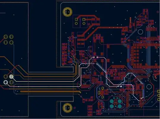
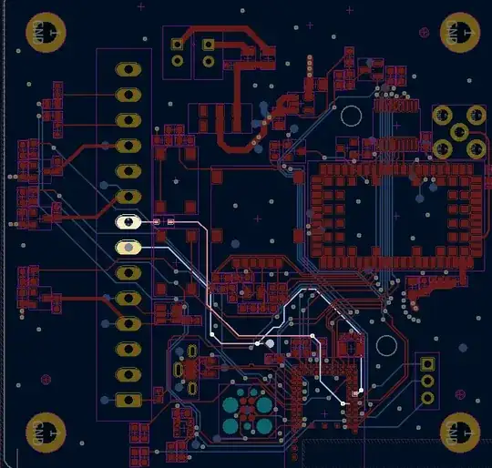
New board, Rx & Tx highlighted (the left hand part only contains connectors, the right hand side is more or less the same as the old board):

New board, not working

Old board, working fine. Nice waveforms.

Old board

Alexander Ohm
  • 341
  • 1
  • 8
  • 1
    Most probable cause = nothing to do with the PCB. – Andy aka Mar 06 '23 at 13:57
  • 1
    What's your stackup? – Polynomial Mar 06 '23 at 14:03
  • 1
    what are the speeds we're talking about? – Marcus Müller Mar 06 '23 at 14:13
  • 1
    Definitely need to know more, such as voltages, frequency, loading, etc – colintd Mar 06 '23 at 14:25
  • 1
    Is the new signal shape causing communication errors or are you just curious as to the reasoning for the altered wave form? Is the change noticed on both Rx and Tx lines, and which is which on the board? As a side note, your routing does seem to have a high number of tangled traces and excessive via use, likely from auto-routing. If you have critical signal lines it is often better to hand route those ahead of auto-routing or to go back and do a final manual touch up. – Nedd Mar 06 '23 at 14:57
  • Is it TTL-UART, or RS-232 or RS-485 or whatever? Baudrate? Share the schematic too! Most likely it has nothing to do with the PCB, like Andy suspects :) – datenheim Mar 06 '23 at 18:59
  • All very valid points, thank you! I updated. – Alexander Ohm Mar 07 '23 at 06:31
  • As Andy says, it's not conceivable that PCB capacitance would affect edges of a glacially slow 115kHz signal like that (assuming it's driven by a normal CMOS output). Something else entirely is going on. – Spehro Pefhany Mar 07 '23 at 07:01
  • The problem was with the cable... Something seems to have happened to it at the same time as I switched boards. With another cable, it looks perfect again. I would submit this as an answer, but the question is locked. Perhaps it should be deleted instead? I found the hints given here in the comments useful, so perhaps someone else does too. – Alexander Ohm Mar 07 '23 at 13:12

1 Answers1

1

The problem was with the cable... Something seems to have happened to it at the same time as I switched boards. With another cable, it looks perfect again. I found the hints given here in the comments useful, so perhaps someone else does too.

Alexander Ohm
  • 341
  • 1
  • 8