Coil flyback is not some magic surge; it's simply the response to the switch's relatively fast turn-off (in comparison to the L/R time constant of the coil).
The current can never be higher than the current at the instant of turn-off, and the voltage is controlled at the switch node first and foremost. Simply putting a diode there, clamps the voltage seen by the switch.
The coil reaction is with respect to the supply. No transient is seen at the supply, aside from the change in load current, and whatever effect that has upon it.
The supply itself may be inductive and show some peak voltage — but that's characteristic of the supply, not of putting a switched coil load on it.
With this in mind, perhaps you may find this anecdote amusing. Or perhaps a little enlightening still:
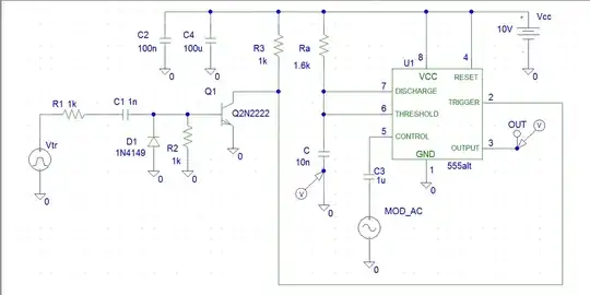
simulate this circuit – Schematic created using CircuitLab
I was once tasked with repairing an electromagnet. This was a heavy benchtop unit, with a pair of thick steel pole pieces on top to hold the workpiece against. The switch was a momentary rocker type, so you hold the piece, tap the switch, BUZZZ, and your part is magnetized. Simple enough. I opened up the housing and observed this circuit. (Component values are vague guesses.)
I might be misremembering whether the MOV was connected across the AC or DC side of the full-wave rectifier (FWB), but in either case, clearly it was an attempt to limit surge voltage across the coil.
If one were switching such a heavy coil on AC mains directly, the switch would experience considerable arcing and wear, and a MOV would be beneficial to suppress the arc energy. It seems this thought process was applied here. The designer/builder did not appreciate that, in fact, the FWB already serves this purpose.
Consider when the switch is pressed: AC is rectified to DC, and current flows through the coil, charging it. [Conventional] current flows in a loop, upward through the diodes, downward through the coil. AC power pushes more current into this loop, through alternate pairs of diodes; near the zero crossings, current decays, dropping through the coil's resistance and the diodes' drop.
When the switch is opened, the coil's current continues, discharging through its resistance and the diodes, in precisely the same loop. Nothing has changed, dI/dt is small, and peak voltage is irrelevant.
I forget what the fault was anymore (maybe just the switch?), but I do recall the MOV was not the culprit.