3

I'm a beginner in electronics and I have some questions about the diagram I made.

  1. Do you have a recommendation for the charger? Or is it easy enough to build one?
  2. R4 is needed or not? I don't know because of the presence of R2.
  3. The voltage divider (R1+R2) is a good choice to lower the voltage for the MOSFETs (max 20 V) or I should do it differently?
  4. I missed something important?

When the power supply is ON, it has to be the source for the power delivery (PD) modules and the charging circuit. And when OFF, the power for the PD modules must automatically be from the batteries.

I don't want to use any mechanical relays and it's OK if I have to do something more complex. My goal is to do something good and to learn what I need for that.

Thank you!


My original diagram Diagram #1

Updated version after the answer of @AnalogKid

Second diagram


Based on this diagram (https://www.microtype.io/lithium-ion-battery-charger-circuit-load-sharing/) Source
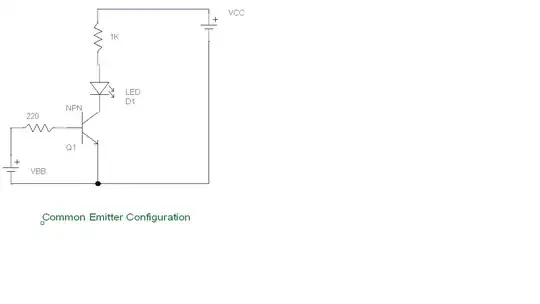

It should be similar to that Model

Davide Andrea
  • 16,164
  • 4
  • 33
  • 62
Mathieu
  • 31
  • 4
  • "The buck converter set the voltage to 16.8v and limit the current to 4A to charge the batteries with the BMS" - so stop right there, you don't have a lithium charger, a BMS is not a charger and neither is a CV-CC power supply because it does not stop charging after batteries are full and charging should stop. – Justme Mar 03 '23 at 16:51
  • @Justme the power supply + the buck converter are taking care of giving a stable 16.8v at max 4A, and the BMS is using it well I think because it has charged my pack twice without problem, balancing the cells and cutting the charge once full. – Mathieu Mar 03 '23 at 16:54
  • 1
    No. Using the BMS to end charging is like not having brakes because you have a helmet or airbag. BMS is the final line of protection when charger fails to do it's job properly for some reason, and in your case, the CV-CC does not even try to stop charging. – Justme Mar 03 '23 at 17:00
  • @Justme Thank you very much for this important detail! So I need to add something between the buck converter and the BMS to stop the power to the BMS at the end? – Mathieu Mar 03 '23 at 17:02
  • 1
    Yes, you should maybe just replace the whole buck converter with an actual lithium charger. Mishandled batteries may damage, damaged batteries may explode or start fires. I recommend not tinkering around with lithium batteries unless 110% sure the circuit is safe, and even then properly designed circuits like EV batteries can burn up like a torch. – Justme Mar 03 '23 at 17:17
  • @Justme thank you, it's a very useful comment I will modify my diagram. – Mathieu Mar 03 '23 at 17:42
  • @Justme I also modified my questions. Do you have any suggestion of charging module? The pack is a 4S2P. – Mathieu Mar 03 '23 at 17:54
  • Asking for suggestions what to buy is off topic, so no I don't have. You might want to edit that out before someone votes closing the question based on that. – Justme Mar 03 '23 at 17:58
  • @Justme I already modified the questions ;) And seriously, it's like that here? Is it because people are unhappy with their life or because it's a common problem that happen too often?? – Mathieu Mar 03 '23 at 18:04
  • You can read the explanation directly from the rules page why they exist. – Justme Mar 03 '23 at 18:21
  • Don't even try to come-up with your own BMS. It's pointless. You don't even know the problems that you need to solve, let alone how to solve them. Just buy a ready made BMS. – Davide Andrea Mar 04 '23 at 00:46
  • 1
    @DavideAndrea don't worry I bought one ☺️ – Mathieu Mar 04 '23 at 01:23

1 Answers1

1

You can delete both R3 and R4.

R3: This does nothing bu lower the effective resistance of R1.

R4: In high-frequency switching power supply applications, a resistor in series with a switching transistor's gate can prevent parasitic oscillations (ringing) caused the gate capacitance and lead/trace/wiring inductance. These oscillations can be at hundreds of MHz, and cause a design to fail emissions testing. In a load switching application such as yours, R4 has no value and is not needed.

Separate from that, if you want to be extra safe regarding the input voltage, place a zener diode in parallel with R1. For example, if the nominal value of the gate R1:R2 voltage is 12 V, use a 15 V zener. Keep R1 in there to assure a quick and complete turn-off of the FETs.

And just to reiterate - Charging Lithium batteries is extremely dangerous. Just ask any attorney for Sony.

AnalogKid
  • 16,865
  • 1
  • 13
  • 25
  • Excellent! I modified my diagram and updated my question. Thanks! – Mathieu Mar 03 '23 at 18:56
  • 1
    The zener is upside-down. Also, there is no GND symbol anywhere in the power train. The FET control signal has to be referenced to something. – AnalogKid Mar 03 '23 at 18:58
  • Thanks again, I changed the orientation of the zener diode. You can see I was not lying when I wrote I was a beginner For the ground, I don't understand. Everything is connected to the same ground? – Mathieu Mar 03 '23 at 19:08
  • 1
    You might know that, but the schematic has three trace segments across the bottom and none of them are indicated as GND. What is shown is that none of them are GND, and none of them are connected directly together. One way to clarify this is to add signal names to each box's connection points, but a more common way is to run one line from the lower output of the supply all the way over to the right-side module, tag it with a GND emblem, and have a short connecting line up to each of the other two boxes. – AnalogKid Mar 03 '23 at 23:14
  • Your comment was useful again I think I will have to start to learn the basics with a good book. I saw too many bad examples everywhere online, and without enough knowledge, it's hard to guess who to trust. – Mathieu Mar 03 '23 at 23:40
  • Is it like that? https://i.stack.imgur.com/otZhL.png – Mathieu Mar 04 '23 at 00:36