4

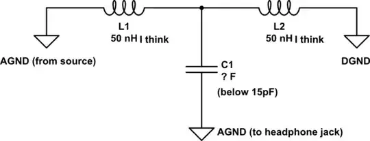
I'm working on an audio circuit, and part of the circuit looks like this:

schematic

simulate this circuit – Schematic created using CircuitLab

What is going on with this circuit? The ground has a lot of noise, and with this circuit I can't hear it at all, so it definitely works. When I get rid of the capacitor, or use capacitor of around 15pF it sounds terrible (filtering audible frequencies). I need to work out the value of the capacitor, but it's too small to measure, so it would help if I understood what's going on to work it out. It looks like a T impedance network, since L and R channels also have this configuration albeit with different values, but I'm not sure.

  • That part alone does not explain much. What do the other parts of the audio circuit look like? – Justme Mar 02 '23 at 19:46
  • @Justme [Here](https://postimg.cc/GHkKrkjt) is an image of the rest of the circuit. The connections labelled RAW are from the source, the others go to the headphone jack – brazed_blotch Mar 02 '23 at 19:50
  • I don't think AGND has enough drive strength in that circuit to work as headphone ground. If you are tracing the circuit, there may be some mistake. Maybe headphone ground is actually GND1 and AGND is just a filter point. – jpa Mar 03 '23 at 06:18

1 Answers1

4

What is going on with this circuit?

They are increasing the high frequency impedance so high frequency current's prefer a path other than from DGND to AGND. Removing the capacitor changes the LC filter to an L and it has worse high frequency preformance.

Voltage Spike
  • 75,799
  • 36
  • 80
  • 208