5

I am taking a PWM input (0-12 V) from a TLC59711 (driven by SPI from a Raspberry Pi) and I want to drive a P-channel MOSFET.

It is driving a 12 V, 40 W LED. I want to switch at high frequencies, as I want the LED not to flicker with any grade of camera.

High definition cameras can shoot up to 1000 fps, so say 5 kHz (or even 10 kHz). I have chosen this gate driver and a p-channel MOSFET. Can anyone see any obvious problems?

I am new to Spice too - just learning.

enter image description here

JRE
  • 67,678
  • 8
  • 104
  • 179
Seb Wilson
  • 51
  • 1
  • 2
    Just wondering, why not drive the LED constantly? – po.pe Mar 02 '23 at 09:06
  • Welcome! You can, but why not simplify things and do your switching on the low side with an N-MOSFET? – winny Mar 02 '23 at 09:12
  • @winny It'd still need a gate driver anyway due to the required switching speed, and you'd still want to be driving \$V_{gs}\$ to around 12V, so it doesn't actually turn out to be much simpler to use an N-channel MOSFET here. For a slow on/off switcher I'd agree, but for PWM the designs are almost identical. – Polynomial Mar 02 '23 at 09:54
  • N-MOSFETs are cheaper for a given voltage and current rating and N-MOSFET drivers are more common. – winny Mar 02 '23 at 11:20
  • @po.pe - Do you have a suggestion to regulate the current that way? Perhaps an inductor to smooth the current after PWM? (Like a buck converter.) If you just use a linear design that drops some voltage across the MOSFET, you'll lose a lot of efficiency to heating the MOSFET. – Peter Cordes Mar 03 '23 at 00:12
  • @PeterCordes, as mentioned, maybe I completely misunderstood the application. But why do you have to use a MOSFET at all? – po.pe Mar 03 '23 at 11:21
  • @po.pe: You don't, but you do need to control the average power output of the LED from 0 to max according to a control signal, apparently already PWM. So you need to map an input signal to a varying average current through it. Switching to achieve the desired average is typically more efficient if you do it right than a power MOSFET or BJT that's partially on all the time. Something like a switching power supply with some output filtering could drive the LED with a near-constant current, without dissipating excess power as heat. – Peter Cordes Mar 03 '23 at 11:26

3 Answers3

7

Your design looks pretty good.

The 10kΩ resistor is a good touch for pulling the gate high during startup.

I'd swap the 0.1uF out for a 0603 35V 4.7uF or 10uF ceramic cap. That'll have nice and low inductance, plenty of effective capacitance at the 12V bias, and the cost bump is miniscule. (And honestly, there's rarely a reason to go with 0.1uF for decoupling anything low voltage these days, unless you're penny pinching for large scale production - large capacitance MLCCs in 0402 and 0603 have become absurdly cheap and abundant.)

Follow good placement practices for the decoupling cap on your PCB - you want as short a loop as possible between the capacitor and the TC4429's power pins. Keep that PDN inductance low!

An electrolytic bulk decoupling cap (220uF 50V, or 330uF 35V) would be a good idea, too, if the leads to your power supply aren't short. With 12V worth of DC bias derating they should give you enough capacitance to maintain a <1V droop for at least 100us, which should be more than enough to compensate for some stray inductance in the power leads. The ripple current is low enough that you shouldn't have to opt for any fancy low-ESR/DF caps here.

Your MOSFET has a nice low gate capacitance and dynamic parameters, so you should be able to get up to around 10kHz 10-bit PWM at the upper limits. 8-bit will be fine. Remember that the shortest pulse length is the period at the frequency divided by \$2^n\$ for n-bit PWM, so at 10kHz you're actually in the ~400ns pulse range with 8-bit, and the ~100ns range with 10-bit.

The only other thing I'd be doing here is adding a 6Ω resistor inline with the gate, and a 1.5Ω resistor and Schottky diode in parallel with it, for asymmetric drive current, like so:

schematic

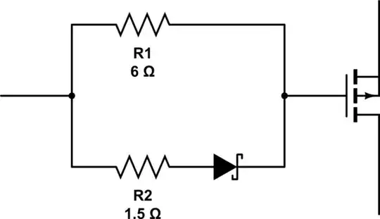
simulate this circuit – Schematic created using CircuitLab

This allows higher gate drive current during switch-off, which helps eliminate the Miller parasitic self turn-on effect. The gate resistance will also moderate gate ringing. 6Ω is the value indicated in the datasheet for the dynamic timings, at a \$V_{gs}\$ of 10V, so it should get you just as good \$T_r\$ / \$T_f\$ with a 12V drive. You may get away without R2 and the Schottky, because it's typically only important in push-pull or H-bridge designs, where you might get shoot-through, but you'll definitely want R1 in series with the gate.

Make sure you design the board layout as compact as possible. Parasitic inductance is really the killer for these kinds of circuits. The path from the TC4429 output to the MOSFET input should be as short as possible. You also really want a good solid ground plane under your traces to provide a low impedance return current path.

Probably goes without saying, but you'll really want to be making a custom PCB for this. Stripboard doesn't give you a reference plane under your traces, TH parts have tons of stray inductance, and it's hard to route tightly on them. Breadboard is right out the window due to the current anyway, but it's no good even for a lower current prototype because breadboards are full of parasitic inductance and capacitance.

You could maybe simplify this design a little with low-side switching and an N-channel MOSFET, but you'd still need a proper gate driver anyway to achieve the necessary switching speed, so it'd be pretty similar. Since you've already picked out a good MOSFET and done the majority of the design work, I'd say it's not really worth it to redo everything.


Addendum: Having slept on it, I had another thought for a potential design improvement.

Your TC4429's decoupling cap is on the same rail as the load, so when there's a switch-on transient the load will try to pull from all local capacitance. If your layout is tight, the MLCC will be one of the lowest impedance sources of energy. It'll probably be fine, but what you could do is add a Schottky diode in series with the 12V rail that feeds the TC4429. This prevents back-feeding the load with the decoupling cap, so all the transient energy is pulled from bulk decoupling and the power source. Since a very short transient droop on the load side voltage isn't critical, but instability on the TC4429's supply might have greater consequences, this could help improve reliability. You'll probably get on fine without it, but it's worth testing.

Polynomial
  • 10,562
  • 5
  • 47
  • 88
  • As for the bypass cap, the Microchip TC4429 datasheet (section 3.1) even suggests a minimum value of 1.0 uF ceramic. The example test circuit uses a 4.7uF and two 0.1uF caps.https://ww1.microchip.com/downloads/en/DeviceDoc/21419D.pdf – Nedd Mar 02 '23 at 09:41
  • Good catch. Given that it's 6Apk out, it's no surprise. I'd probably personally opt for the 10uF 0603 35V option here, and maybe even throw a second one on in parallel for peace of mind. Although if the layout is good then the PDN inductance should be low anyway, especially with some added bulk decoupling, so one should suffice, and a second cap footprint would probably increase the loop size due to via placement, so it might not be optimal. Probably just splitting hairs though. – Polynomial Mar 02 '23 at 09:45
  • Beware, a 10uF 0603 won't be anywhere near that at 12V. 1206 more likely keeps reasonable value up there. Always check the characteristic sheet for the capacitor. – Tim Williams Mar 02 '23 at 16:26
  • @TimWilliams I'm accounting for the DC bias derating, hence the 10uF 35V part suggestion. I did some rough PDN calculations based on a 60% capacitance derate, and there's still heaps of headroom. – Polynomial Mar 02 '23 at 19:10
  • Hmm, just taking a look at DK I see only *six* 10uF 35V 0603 parts in the catalog, all of them X5R only; and the most common one (there are half a million in stock at least!) is Murata GRM188R6YA106MA73D, which is -85% at 12.1V. In contrast, Samsung CL21B105KAFNNNE is 1uF 25V X7R 0805, well stocked, and only -15% at 12V; or CL21B225KAFNNNE is -46% at 12V (almost identical value lol). – Tim Williams Mar 02 '23 at 19:26
  • @TimWilliams A little higher than expected, certainly. It'll still be fine for a 400ns length transient at >6A though, keeping the rail high enough to stay above the gate voltage that the MOSFET's dynamic parameters are rated for. Could be worth jumping to 0805 with a lower DC bias derating if the layout can be kept tight. – Polynomial Mar 02 '23 at 19:44
  • 1
    For a given footprint and height, most higher capacity class 2 MLCCs will have about the same effective capacitance at 12v regardless of nominal capacitance or voltage rating. For example at Murata, all larger 0603s have about 1.4-1.5uF at 12v. There is also no point in picking these high voltage capacitors if you only need 12v. It doesn't help with DC bias. – user1850479 Mar 02 '23 at 19:45
  • A smaller driver or larger gate resistors can also be chosen; the shoot-through from the driver itself isn't all that much, and in the present case at least I guess, very little gate current should be necessary since the load is so small. – Tim Williams Mar 02 '23 at 20:33
  • @user1850479 Thanks for the reminder. I should've known it was about material volume, given that I recently wrote an answer about spontaneous polarisation reversal inhibition in barium titanate MLCCs, but for some reason I had it in my head that a higher voltage rating assisted with derating. – Polynomial Mar 03 '23 at 23:27
  • Thank you so much for all and what a warm welcome. I wish I'd joined earlier!! So all things considered I think I'll stick with PWM switching for now. I'm thinking I'll add the 220uF cap for the PSU as leads nnot very short, a schotty on the pwer rail to the TC 4429 (any suggestions for the device?) the 6 ohm and 1.5 ohm and schotty in parallel to mosfet gate (any suggestion on schotty device and power rating of resistors?) and 4.7-10uF decoupling caps as suggested. I asuumer that will be better and more robust..? – Seb Wilson Mar 04 '23 at 12:06
  • This might be a silly question (I'm always learning) - as the TC 44429 is rated to 6A - there's no chance it will allow too much current to the gate of the mosfet is there? I mean at 100% PWM duty cycle - how much current is going into the gate of the mosfet? Thank you again, really appreciated everyone – Seb Wilson Mar 04 '23 at 12:07
  • @SebWilson The current that flows is a result of the voltage applied to the gate, the gate's charge voltage, and the resistance of the path. At 100% duty cycle zero current is going to the MOSFET gate - current only flows at switching transients. You can't really send "too much" current to the gate in the sense that it'll damage it, but excessive drive current on the gate will cause ringing and noise. Adding the 6R (and optionally Schottky + 2R in reverse) resolves this problem. Regarding parts for the gate drive, you can use any fast Schottky diode capable of handling a 6A pulse for <1us. – Polynomial Mar 04 '23 at 23:48
  • @SebWilson Regarding power rating, it's such a short pulse and low resistance that I wouldn't worry too much. 1/4W would be fine. 1/8W is probably fine too. – Polynomial Mar 04 '23 at 23:50
  • I've uploaded my amended circuit (had to upload via a new answer below. Hopefully I've got interpreted the answers correclty - could you kindly offer some suggestions for the schottky's please? Thank you for any pointers – Seb Wilson Mar 10 '23 at 00:19
4

There is no reason to actually switch the LED at all. The PWM output, switched via a half-bridge (one PMOS, one NMOS), drives an inductor that converts the PWM voltage into a small amplitude sawtooth current. That can be further filtered with a capacitor. So the LED sees constant current and doesn’t flicker, and you’re not dissipating much power either.

The frequency of the PWM affects the inductance and the capacitance: the lower the frequency, the bigger these two get. So it’s usually a trade-off between size and dissipation. Higher frequency has higher switching losses and potentially higher dissipation in the capactor, but the components get physically smaller the higher the frequency - up to a point where the output power drives the component sizing due to conductive losses and such. At 10kHz you’re far, far away from such limits and in fact you could make the thing smaller by going up in frequency to, say 50-100kHz.

Most generally speaking, any motor bridge driver chip with suitable current rating will do this job. They are designed to drive inductive loads - in your case, the smoothing inductor.

The only reason we have PWM LED flicker is because of cost cutting. To get rid of flicker, add a complementary MOS device or a free-wheeling diode, an inductor, and a capacitor. The full-amplitude PWM current tends to be an EMC concern, and the cables for some even low power LED lights radiate like crazy.

1

I made an LTspice simulation for a similar application for another recent question. The current limiter is not really needed, but may be useful.

PWM LED with inductor

In order to maximize efficiency of an LED drive circuit, an inductor can be used. In this circuit, the MOSFET is driven by a PWM signal. When the device is turned on, current will flow through the LED and the inductor, and when the MOSFET is turned off, the current in the inductor will flow through the flyback diode D2. This process will continue and overall current will increase until the energy added to the inductor during the ON time matches that which is expended during the OFF time of the PWM signal.

This is continuous conduction mode (CCM), and the duty cycle becomes critical as average current is increased. I arrived at the values I used in the simulation by trial and error. Other values could be chosen where duty cycle is not so critical, but at the expense of increased ripple. Eventually it will be running in discontinuous conduction mode (DCM), where all energy stored in the inductor will be dissipated during the OFF time. But that results in very high ripple.

PStechPaul
  • 7,195
  • 1
  • 7
  • 23