1

I have built a power supply using an LM317:

schematic

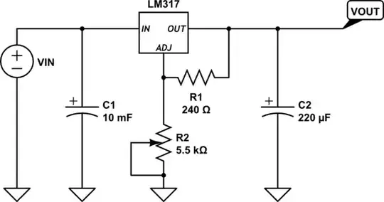
simulate this circuit – Schematic created using CircuitLab

When the supply is on for a rather long time (several hours) with a respectable load, the output voltage increases in the order of several hundreds of millivolts. I think this is because of the warming up of the LM317. I already have a heatsink, but the IC is still getting hot, especially with a great load and a long on time, of course.

I was wondering if there would be any way to make some kind of protection to make sure the voltage doesn't change too much. I've thought of these options:

  • Adding a PIC on a separate 5V supply which monitors the supply and beeps when it changes too much. This might be an overkill for such an easy problem.
  • Adding a PIC and make R2 a digital pot, so that I can digitally set the output voltage, and the PIC takes care of the rest and automatically changes the resistance on the adjust pin when the output voltage changes. Again, an overkill, and I don't want to have a lot of work for this.
  • Something with a comparator, but that gives a problem with that the supply is variable. I'm not sure how I could work this out with a comparator...
  • Bigger heatsink, better placement, adding a fan - would probably work indeed, but I feel like there should be an electrical solution (i.e. with adding a circuit) and I'd like to see that solution.

So, what would such a solution with a circuit look like?

Here are two photos of my setup:

enter image description here enter image description here

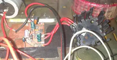
First, on the right: the heatsink with the LM317
First, on the left: the board with R2 somewhere
Second, bottom: the two pots (5K and 500) that are R1 together

  • What is the current draw? Are you exceeding the rating? – Scott Seidman Apr 14 '13 at 12:17
  • @ScottSeidman 100mA, the LM317 is rated for 1 or 1.5A, I believe. –  Apr 14 '13 at 12:19
  • You should bypass R2 with a capacitor to improve transient response. See the datasheet. – user207421 Apr 14 '13 at 12:33
  • 1
    Are R1 and R2 mounted in a way that they also heat up together with the LM317? – AndreKR Apr 14 '13 at 12:33
  • That's an odd one. Vref goes down with temperature above 25ºC and that would lower the output voltage. I adj goes up about 4uA from 25ºC to 100ºC but that would only increase output by 20mV. Very odd. Try checking the the voltage across R1 - how does this alter with temperature? Does the load get smaller with temperature? – Andy aka Apr 14 '13 at 12:34
  • @EJP that isn't done in the schematic on page one of [this datasheet](http://www.ee.buffalo.edu/courses/elab/LM117.pdf)... –  Apr 14 '13 at 12:44
  • @Andyaka the temperature only increases for the LM317, so it doesn't have effect on the load or R1. Do you still want me to measure the voltage over R1? –  Apr 14 '13 at 12:45
  • R1 should reduce from 1.25V at ambient which has to mean the output goes down with temperature. Measuring it might inform you that you have a bad device but it seems unlikely Camil. It's very odd. I've used a couple of 317s in my past and don't ever remember seeing them move anything like a 100mV – Andy aka Apr 14 '13 at 13:14
  • possible duplicate of [LM317-based adj power supply output takes a while to stablize](http://electronics.stackexchange.com/questions/25970/lm317-based-adj-power-supply-output-takes-a-while-to-stablize) – Anindo Ghosh Apr 14 '13 at 13:16
  • How much is Vin? – pjc50 Apr 14 '13 at 14:22
  • @pjc50 around 17V (12V~ rectified). Vout was 5V, when the problem occurred. –  Apr 14 '13 at 14:23
  • Is your schematic missing a connection from the wiper of the pot to ground? I calculate 30 V output for the circuit as drawn. – The Photon Apr 14 '13 at 15:15
  • @ThePhoton thanks for the cap-note. I couldn't draw it correctly with circuitlab, let me try that again. It indeed should be connected to ground. –  Apr 14 '13 at 15:17
  • 1
    To people who voted to close as duplicate, the question Anindo linked has a circuit where output drifts down over time. This question has output drifting up. This suggests a different root cause of the drift, and not a duplicate question. – The Photon Apr 14 '13 at 16:00
  • Buffering the output would reduce the load. Better stability can be had using a temperature stabilized voltage reference (LM299 0.0001%/°C temperature coefficient). There are circuits online to use the chip. – Optionparty Feb 02 '15 at 00:05

2 Answers2

6

This answer is a bit speculative, but its my best guess what's going on.

To get 5 V output, you have your pot turned to get about 720 ohms for "R2". It's got (5-1.25 =) 3.75 V across it, so it's burning about 20 mW. Even though you don't feel it to the touch, it is heating up inside. A pot is probably a relatively large part, which helps explain the very large time constant you're seeing on this voltage drift. Check the datasheet to see if the pot has a postive tempco, or hit it with a hot air gun and watch the output as a first step to confirm or reject this as the source of error.

Another slightly less likely effect, also involving the potentiometer, would be if thermal effects are causing the wiper resistance to drift, or if a chemical change (like oxidation) is happening at the contact of the wiper to the resistive element over time. Since the wiper is part of the "R2" controlling your output voltage, any effect on the wiper resistance will also cause your output to drift.

Depending what kind of pot you're using, and if you really need adjustability, you could try changing to a higher quality pot with lower tempco and known wiper resistance stability, or switching to a fixed resistor, and see if the drift is reduced or eliminated.

The Photon
  • 126,425
  • 3
  • 159
  • 304
1

From the image above, the heatsink maybe inadequate for your load. Solution:

  1. Use a bigger heatsink. Produced heat is directly proportional to the Input voltage and from the load of the regulator.

  2. Check the input voltage. An input of 9V for 5V output is OK.

For a great load, boost the output of the LM317 with additional power transistors with heatsink. The number(NPN transistor) depends on how high the current output rating of your transformer.

Rommel
  • 21
  • 3
  • To prevent or minimize heat on LM317, another suggestion would be to boost the output of the LM317 with NPN power transistor. – Rommel Feb 01 '15 at 08:33