0

I recently asked a question on why my naive implementation of a XOR circuit in CMOS was wrong.

One of the most mentioned issues was that I had a floating node in my diagram. I've looked up floating nodes, and I understand the idea that they're signal lines without a well-defined voltage. I'm also aware that this can cause erratic behaviour in a circuit. However, I can't find any examples of what strange behaviour this causes.

What are some common issues that floating nodes cause?
Connor
  • 375
  • 1
  • 8
  • 2
    In your case the bottom transistor will remain on, even if the left side transistors turn off, because there is nothing to make the bottom transistor turn off. Until some random cosmic rays bump into it by chance, and make it turn off. – user253751 Mar 01 '23 at 10:47
  • @user253751 I see, so the charge on the rail remains, even if the power that initially charged it is gone? – Connor Mar 01 '23 at 10:48
  • 1
    yup. The bottom transistor's gate acts as half of a capacitor. Well, every unconnected wire acts like a capacitor, but we don't care, unless it's connected to a gate and keeping the gate open. – user253751 Mar 01 '23 at 11:07

2 Answers2

6

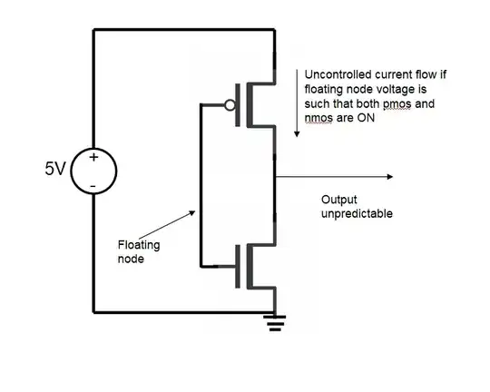
With this simple case that I drew below, you can see that a floating node can cause

a) unpredictable output. Gate leakages generally determine the voltage of the floating node in this case and we can never say what voltage the floating node will settle to. If there is a routing running close to this floating node, the capacitive coupling between the 2 lines can also disturb the voltage on this line as it is very high impedance.

b) unexpected current consumption. Normally the gate of this inverter is 0 or 5V. So, either NMOS is OFF or PMOS is OFF. However, if the node settles to say 2.5V, both PMOS and NMOS are strongly ON and can cause huge leakage from the 5V supply to ground depending on the drive strength of this inverter.

enter image description here

sai
  • 3,352
  • 1
  • 2
  • 13
  • What are gate leakages? Why is the line high impedance? Is it because current can't easily flow along the line? Is the lack of current flow what causes its voltage to be so strongly affected? – Connor Mar 01 '23 at 13:18
  • How bad could the leakage be in this situation? Melting the circuit board bad? – Connor Mar 01 '23 at 13:19
  • If your gate is a discrete IC, there won't be any uncontrolled current flow as in shoot though. It may toggle very fast, causing losses, but not uncontrolled current flow. – winny Mar 01 '23 at 13:22
  • @winny, why do you say that there will not be uncontrolled shoot through in case of a gate that is a discrete IC? – sai Mar 01 '23 at 13:33
  • 1
    @Connor, a net is very high impedance if there is no path from that net to any other low impedance net like supply or ground. Since the impedance on that net is purely capacitive, at DC, the impedance of that net is theoretically infinite. So, even small leakage currents flowing into these nets can change the voltage significantly. Gate leakage of a transistor is the current flowing into the gate from other terminals of the MOSFET (Source, drain, bulk). – sai Mar 01 '23 at 13:47
  • 1
    @Connor, Regarding the uncontrolled current, the magnitude is very much dependent on the size of the MOSFETs. If the MOSFETs are small, it may not cause any board issue. So, you'll really need to simulate the case or test it in the lab to find out. – sai Mar 01 '23 at 13:48
  • @sai What do you mean by "net"? Is that the name of this particular type of floating node? – Connor Mar 01 '23 at 14:11
  • The IC manufacturer will make sure that does not happen, either by Vgsth tolerances or other means. If there is shoot-though on each switch, thematic logic gate is a lousy one. Simulate it better yet, buy one and measure yourself. – winny Mar 01 '23 at 14:36
  • @winny, I have measured supply current on some micro-processor ICs and I do see increased leakage when an input pin is left floating. With discrete logic gates I have not tried doing this. Will try it when I get the opportunity but I don't see why there will be no shoot-through. Atleast the first inverter connected to that floating pin will leak but that will be a small leakage because it will low strength inverter. At the output of the first logic gate, the output usually gets resolved to logic high or low due to the inverter gain. So, I don't expect leakage issue for following gates. – sai Mar 01 '23 at 16:49
  • @sai What do you mean by the term "net" in your previous comment? – Connor Mar 02 '23 at 10:18
  • 1
    @Connor, every wire in the schematic is called a net – sai Mar 02 '23 at 12:21
2

So what can happen in your circuit does not itself depend on how the floating node can affect the logic state, it really depends on what your circuit does with the logic state it receives, as the state may not be what is expected.

A floating node can be randomly stuck to either logic 1 or logic 0 and can also change randomly due to any effects such as leakage currents or nearby RF transmitters.

If the floating node connects to two inputs, one might interpret it as logic 0 and the other as logic 1 if they have slightly different thresholds deciding between 0 and 1.

On analog level, a voltage at the input threshold for an CMOS input will turn both the NMOS and PMOS transistors halfway on, so extra shoot through current can constantly pass from supply to ground.

Justme
  • 127,425
  • 3
  • 97
  • 261