4

I need to power a single CW laser diode with a constant current source. I have attached the datasheet of the laser. It is a 2.2-2.4V laser whicht operates at 80mA at full brightness.

I see a lot of constant current circuits online but they all have a potentiometer to set the brightness. I want my laser at full brightness, always.

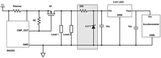
I saw the topic that uses the TL431 as a current limiter where they made a circuit to power multiple LEDs. I copied and changed the circuit to my requirements, and built the circuit myself.

The problem is that when I power the circuit the laser shines really low and it gets very hot. After a minute or so, the laser eventually turns off. The whole circuit has to be powered by a 3.7V LiPo battery. Is this the right type of circuit for this application but I have to adjust it, or do I need a whole different type of circuit?
Datasheet Laser

enter image description here

enter image description here

JRE
  • 67,678
  • 8
  • 104
  • 179
  • 2
    *they all have an potmeter to set the brightness but i want my laser at full brightness, always* What stops you from just setting the potentiometer once for full brightness and leaving it that way? Or subsequently replacing it with a pair of fixed resistors? – Kuba hasn't forgotten Monica Feb 27 '23 at 16:14
  • Leon, you say that it can operate up to 80 mA. But look at the curve you added, when at 25 C. They don't run the curve out to 80 mA in that case. Possibly for good reason. What is the peak current you actually expect to apply? And, when applied in its final application (not testing), is it to be pulsed or continuous? Over what temperature range will the rest of the circuit have to operate, correctly? Will you be making more than one, where each must produce similar optical output, very closely? – periblepsis Feb 27 '23 at 22:31
  • Your laser diode is likely dead now. – Massimo Ortolano Feb 28 '23 at 10:45
  • You'll need a heatsink for the laser diode. – datenheim Mar 02 '23 at 09:49

6 Answers6

7

That circuit will not work for what you want. First, your resistor values are wrong.

$$ I_O = \frac{V_{ref}}{R_{sense}}$$

So rearranging the formula, for 80 mA you would need

$$ \frac{2.5V}{80mA} = 31.25\Omega$$

Also the 100\$\Omega\$ resistor is too small, 10k would be more reasonable.

But the big problem is you need to drop 2.5 V across the sense resistor, and more than 2 V across the Laser diode, so you're over your supply voltage. To make this work you need a higher supply voltage or less voltage drop in the current source.

Here's a simulation, you can see with a \$V_{LED}\$ of around 2.3 V the output current doesn't stabilize until the supply voltage is around 7 to 8 Volts.

enter image description here

A current source needs to be able to vary the voltage across the load, so you need to know how much that will vary, plus how much voltage you need for the sense resistor, and how much for \$V_{ce}\$. If you're going to use a 3.7 V battery to power a 2.4 V diode you'll need to reduce the reference voltage requirement and \$V_{ce}\$ to less than 1.3 V. A much smaller sense resistor and an opamp might do it, look into opamp based current sources or a transistor instead of the TL431.

Based on Sredni's comment I simulated a typical transistor based CCS and it looks like this is what your original circuit was designed for, the resistances you had work pretty well.

enter image description here

This looks like it will work with the 3.7 V battery, although the regulation is a bit worse.

GodJihyo
  • 17,628
  • 1
  • 16
  • 45
  • 2
    Maybe use a simple BJT instead of the TL431. That'll add only a 0.65V overhead. – Sredni Vashtar Feb 27 '23 at 18:11
  • @SredniVashtar Yes, that would work. Now that I look at that it looks like the original circuit was probably designed for a transistor, 10 and 100 ohms works out about right,. – GodJihyo Feb 27 '23 at 18:26
  • I simulated one with two 2n2222, R1 2.2k, Rset 8 ohms and it gives between 74 and 80 mA over 35 to 50 degrees Celsius. With 3.7v battery. Of course, if the OP needs better temp stability something else needs to be added... – Sredni Vashtar Feb 27 '23 at 18:29
  • @SredniVashtar I would have to play around with the values to optimize it, R1 can be a higher value, different transistors may work better, I think we're going in the right direction though, thanks for your input. – GodJihyo Feb 27 '23 at 18:58
4

Measure the current through the LED and make sure you are not going over 80mA, you would probably want to run it more of the recommended 75mA. 75ma * 2 volt drop is 150mW so I wouldn't expect it to get too hot but you may need a heat sink.

Voltage Spike
  • 75,799
  • 36
  • 80
  • 208
3

Two things jump out at me.

"it gets very hot."

Yes, it does. You need a heatsink.

Second - that circuit is not possibly working properly.

Start at ground and work up. Assume that the voltage reference is working properly. Then the emitter voltage of the BJT is 2.5 volts, and the current is 0.25 amps. Then the voltage at the supply MUST be at least 5.1 volts, and probably more like 6 or 7.

What seems to be going on is that reference voltage is much lower than normal, and your current source is pulling much less current than you expect. So your laser is not nearly as bright as you want. I suspect that the simulator model for the voltage reference is simply not accurate in the current operating conditions.

"The whole circuit has to be powered by a 3.7V LiPo battery. Is this the right type of circuit for this application but I have to adjust it, or do I need a whole different type of circuit?"

Probably a different approach. A maximum laser voltage of 2.6 volts (from the data sheet) means you have no more than 1.1 volts to play with for a current regulator. I've no experience designing at these low voltages, so I can't give you advice.

WhatRoughBeast
  • 59,978
  • 2
  • 37
  • 97
3

You can use V(BE) of a transistor (here: Q2) as a voltage reference. R1 sets the current: the higher the value, the lower the current.

schematic

simulate this circuit – Schematic created using CircuitLab

The circuit performs acceptably:

Laser diode current vs. supply voltage

1

I suggest you add two feedback circuits, current & brightness & temperature.

Use the PD to detect the laser starting and regulate its output with current limiting.

You also need heatsinking with thermal feedback on the laser case as it is the high heat that causes efficacy to fall before shutdown. Attempt to design it to not burn your finger or 55’C max.

If you do not have enough heatsinking you may choose a current that results in either short life or thermal-runaway.

Hoagie
  • 1
  • 4
0

The maximum ratings are specified for a case temperature of 25degrees Celsius.

For 83 mA you will need a heat sink.

RussellH
  • 12,496
  • 2
  • 9
  • 34