I am trying to build a circuit using the signal from a Fuji XT-20 camera hot shoe to drive an interrupt input pin on a Teknic ClearCore controller.
My understanding is that all the hot shoe does is when the camera fires, the middle (trigger) and side (ground) pins are shorted (as also explained in this thread). I have confirmed this by connecting the contacts from the hot shoe to an interrupt input of my controller, and when I manually trigger the camera, it seems to behave just like a switch input.
However, it looks like if the ground from the camera hot shoe and the one from the ClearCore are commoned, the camera stops triggering when it receives a trigger signal from the controller, which is problematic since I am not looking to trigger the camera manually but programmatically.
I have built the circuit below using an optocoupler (the ISQ74) to keep the 9V camera power supply and the Clear Core power completely isolated.
My expectation would have been that when the hot shoe is in its normally open state, 52 mA flow from the camera power supply through the optocoupler LED, activating the phototransistor causing the ClearCore input to register a logic high. As the camera triggers and the hot shoe closes the contact, current will flow straight through ground and the optocoupler will stop conducting, making the ClearCore register a logic low.
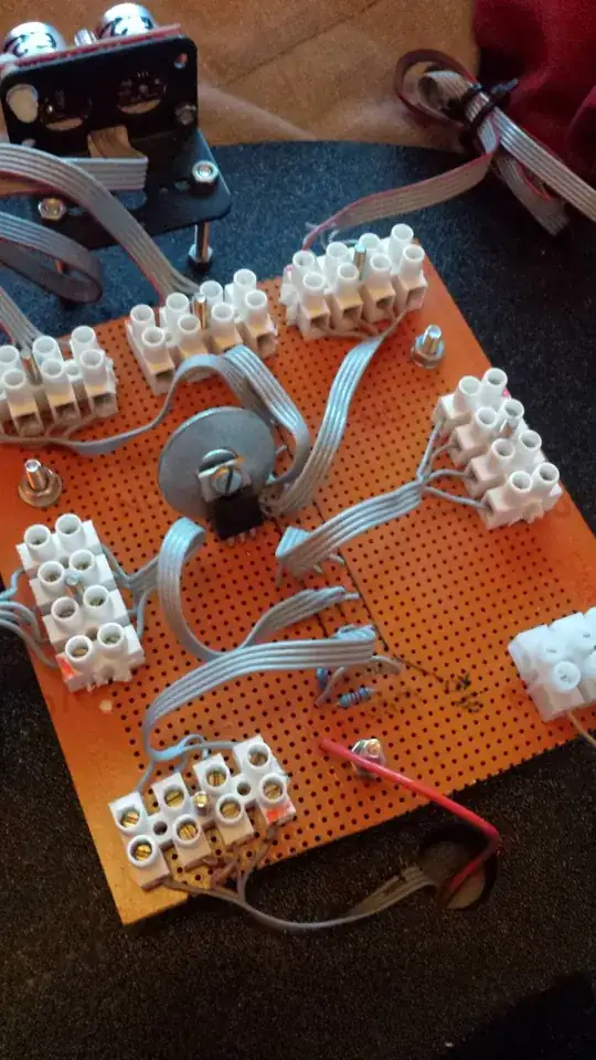
This seems to work when connecting the circuit to a bench power supply - if I simulate the hotshoe using a jumper wire, I can measure continuity at the opto output when the switch is open and an open circuit when the jumper connects to ground. However when I try integrate it with the rest of the hardware, the LED seems to be conducting no matter whether the hot shoe switch is open or closed, and the ClearCore input is always "high".
What's even more bizarre is that manually shorting the hotshoe contacts with a jumper seems to yield the desired results.
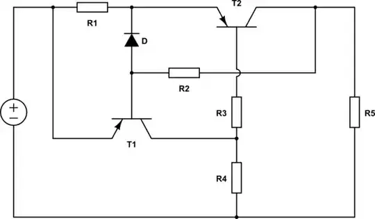
Edit: below is the circuit I am looking to build to address the points made in the comments:
The potential divider would drop the camera power supply down to 5V at the point where the hot shoe and optocoupler connect. R3 Limits the current going through the optocoupler LED to 50mA when the hot shoe is in the open state. When the hot shoe shorts, 1mA is sunk to the ground and no current flows through the LED. Would this work as I have described?

