0

In electronic circuits, for binary operations we use on as 1 and off as 0. Like in the data transmitted through fiber optic cables is sent using light going on and off. How can an output be generated with a 0 input being given by no signal/current-voltage being 0/circuit off?

For example, consider a NOT gate. It simply toggles the input when current passes (input=1) output is the LED turned off. For input=0, no current passes through the gate. How can the gate turn the LED on without any supply?

In a nutshell, how can no signal be an input signal, as in any normal time when you don't want to give any input, even then it's a no signal condition. That way 0 will always be a constant input to any digital circuit, right?

These kinds of anomalies with binary system through on/off is what am not understanding.

Is it as if that NOT gate has its own power supply, and it simply checks the input and generates output with its own power? Then is it so with all digital systems, and does the input current then never power the output ever?

JRE
  • 67,678
  • 8
  • 104
  • 179
  • 3
    All digital logic gates have their own power supply. Have you looked at any datasheets for the common old 74xx series? – brhans Feb 21 '23 at 16:53
  • 4
    Digital gates are provided a power supply, and that's where the power to the output comes from. Also, digital signals are usually voltages rather than currents. – Null Feb 21 '23 at 16:54
  • 2
    Although a binary signal can *mean* "on" or "off" (for example, a ATX computer power supply has a signal from the power button), those aren't descriptive of what is actually happening. "Low" and "High" are descriptive. And you will find the more generic meanings are "Asserted" and "De-asserted" (notice that for an "active low" pin or signal, "High" means "De-asserted"). "High" and "Low" themselves are shorthand, they could be High and Low voltages relative to ground, High and Low voltages between a differential pair, forward and reverse currents, etc. – Ben Voigt Feb 21 '23 at 18:00
  • 3
    "In electronics circuits, for binary operations we use on as 1 and off as 0." Sometimes, maybe, but not always. Something could be ON with a 0. – SteveSh Feb 21 '23 at 18:14
  • 1
    @LumbiniAshutoshTambat a gas pedal in an automobile is like the input to a logic gate ... it does not actually move the vehicle – jsotola Feb 21 '23 at 18:25
  • 2
    And like Ben Voight said, I find the the terms "asserted" and "un-asserted" to be much less arbitrary and confusing than terms like ON/OFF. – SteveSh Feb 21 '23 at 18:27
  • What does asserted mean? Is it like giving something in or highlighting, so +ve? – Lumbini Ashutosh Tambat Feb 21 '23 at 20:21
  • When a signal is asserted, it is doing what it's name suggests (I know, kind of convoluted). For example, you would say "the XFER_CMPLT [signal] is asserted when the bus transfer has completed". This statement does not depend on whether the XFER_CMPLT signal is active low, active high, or even a pulse. I first came across this terminology in the documentation for the early versions of the VME Bus, in the early 1980's. – SteveSh Feb 22 '23 at 00:49
  • Very similar question asked a few days ago: https://electronics.stackexchange.com/questions/655233/logic-gate-electricity-voltage-and-meaning/655246#655246 – winny Feb 27 '23 at 18:42

4 Answers4

4

...that NOT gate has its own power supply, and it simply checks the input and generates output with its own power? Then is it so with all digital systems, and does the input current then never power the output ever?

This is correct. There may be rare exceptions, but modern digital systems all operate in this way.

You have correctly identified that a NOT gate (inverter) is unable to provide a high output using power from a low input (since there's no input power), but it is possible for an AND or OR gate to do so, since a high output can only occur when one or more inputs are also high.

Here's an example of an OR gate which produces a high output using only the inputs as a source of power:

schematic

simulate this circuit – Schematic created using CircuitLab

If the potential at any input (A, B or C) rises (a "high" input signal), then its corresponding diode begins to conduct, "raising" the output voltage to almost the same level.

Modern systems are more sophisticated, and they derive their outputs from a separate power supply, as you noted. This is a picture of the connection pins for an IC that contains 6 inverters, the 74HC04 (which I borrowed from TI's datasheet, page 1):

enter image description here

The two pins 7 (GND) and 14 (Vcc) are where we connect an external power supply. They are a source of low and high potentials (representing logic 0 and 1 respectively) that the IC routes internally to those six outputs, depending on what it "measures" at the corresponding inputs.

TonyM
  • 21,742
  • 4
  • 39
  • 62
Simon Fitch
  • 27,759
  • 2
  • 16
  • 87
  • 2
    Note: Complicated logic circuits are **not** designed using gates like your one, because the signal gets weaker when it goes through each gate, and eventually, there is no signal left at all. However, a circuit like this might be used in some cases, if you just need one or two gates. – user253751 Feb 21 '23 at 19:18
  • A low potential can be anything lower compared to the higher one or 0V only? – Lumbini Ashutosh Tambat Feb 21 '23 at 20:15
  • 1
    Each digital logic family has its own specifications. For TTL (7400 series) a low input signal is 0 to 0.8 volts and a high is 2 volts to 5 volts. For a set of compatible logic elements the actual voltage ranges that are interpreted, respectively, as a logic 1 and a logic 0 could be anything not overlapping. A hypothetical system could have its 0 represented by a range at higher voltage than the range for its logic 1. – George White Feb 22 '23 at 00:03
1

Or is it that a NOT gate has its own power supply, and it simply checks the input and generates output with its own power? Then is it so with all digital systems, and does the input current then never power the output ever?

Yes. Modern digital logic is all CMOS, and in CMOS, inputs are an open circuit: the input is literally isolated from the MOS channel by a layer of silicon oxide. CMOS is voltage controlled, not current controlled, so it's the voltage at the input that determines how the input is "perceived" by the chip, not current. CMOS inputs are approximately open circuit when the input voltage is between the I/O power rails.

In practice, when the input is not DC but switches between the logic states, there is some AC current flowing through the gate capacitance, ESD protection network, and package parasitic capacitances. But the DC current flowing into/out of a CMOS IC digital input is mostly the leakage current through the input protection diodes and so on, and at room temperature can be well below 1µA. Pretty close enough to an open circuit.

Even in pre-CMOS logic, e.g. NMOS or transistor logic, the outputs were driven by their own active device. For example, in TTL, when the input is at a high level, no input current flows, and the input can be left completely open and still act as a high logic level. This is not the case with CMOS logic, where an open input typically causes the circuit to misbehave randomly, and typically only when it costs real money (e.g. failures in the field or during an important demo).

0

I think what’s confusing you is the notion that a logic ‘0’ represented as a zero-volts value is somehow ‘no signal’. It most definitely is: it’s a voltage that’s being held at 0V by something, referred to system GND. Sender and receiver agree on this shared understanding of '1' and '0' being referenced to GND.

A CMOS logic low is in fact a low-impedance connection to GND, not an open circuit. CMOS logic signals are explicity driven high or low by FETs.

You can think of a CMOS output as a single-pole double-throw switch that ties the output either to GND or the power supply. The NOT gate is the simplest of these, with just the FET pair, doing its SPDT thing.

Here's a CMOS NOT gate you can try for yourself (simulate it here)

enter image description here

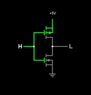
You can see the action of the FET pair, connecting the output to either +5V or GND depending on the input. To function, it needs both a power/GND connection, and an input signal that is referred to GND to guarantee correct voltage to the FET gates.

Other logic families are similar: the driver always guarantees a valid voltage level representing either a one or zero, referenced to GND. Their inputs are never left 'disconnected'.

NOTE: In some logic families, a disconnected input will assume a logic level. TTL for example will assume a '1' due to its diode-OR type input structure with a local pull-up. This is not recommended practice. You can explore this further in Falstad, which has examples of TTL, DTL, RTL and other gates (see Circuits/Logic Families.)

As you touched on, voltage isn’t the only way to represent logic. The absence or presence of light, or magnetic flux, or current, or sound, or some other physical phenomenon can also do this. As long as there is agreement between transmitter and receiver, logic levels can be sent reliably from one place to another.

When there isn't a shared voltage reference, some transmission methods instead encode 1’s and 0’s not as static signals, but as changes in some other signal. A primitive example of this would be frequency-shift keying, or FSK, where a carrier tone is frequency-modulated by a digital signal. FSK probably best known for its use in 300 baud modems.

A benefit of using FSK is that there is always a carrier present: the receiver knows that it has a link established with the transmitter, even when there is no data being sent (or, it's a run of zeroes.)

Similarly, the digital audio SP/DIF standard has both a wired (coax) and optical version (TOSlink.) TOSLink turns a LED on and off to send a binary stream down a fiber optic cable. But it sends something all the time: a clock combined with the data stream using a technique called differential Manchester (or biphase-mark) coding.

Thus, SP/DIF coax and TOSLink are always sending something, even if the data it is sending are all zeros (or, not valid). Again, like FSK, the coax or TOSLink receiver knows a link is present even if no data are being sent. There is a baseline established even without a physical ground connection (SP/DIF can, and often is, AC-coupled via isolation transformers, especially in its pro-audio AES version.)

Stepping back, understand that for valid transmission of data to take place, the sender and receiver have to have a shared understanding of not only what defines ‘1’ and ‘0’, but of a baseline reference for a link to be formed. For a local logic system that is usually the power supply reference. If no such reference exists between sender and receiver, it needs to be agreed upon in another way.

hacktastical
  • 49,832
  • 2
  • 47
  • 138
0

People who want their digital designs to "work" design them in such a way that they understand what will be output for any situation likely to arise. With that in mind, if it's important, we learn to tie all inputs that may "float" to either logical high or ground voltages through a resistor, which we call "pull-up" (or pull-down, depending on the direction) resistors. If we use a relatively low-valued resistor, we would call the configuration "strongly" pulled-up, or a very large resistor would result in a weak pull-up.

Floating inputs are not the only issue digital designers need to deal with. If you have circuit elements with any memory, such as flipflops or latches, then you need to worry about the initialization state of the outputs. There are supervisory circuits for power-up situations that can help you get access to what you need to generate output enables and reset pulses, and the like. This can get pretty complex.

In sum, if it's not particularly important to the functionality of your system, you may not need to do anything. If there's a possibility that floating inputs or random initialization states can mess you up, you do what you need to do to deal with it.

Scott Seidman
  • 29,274
  • 4
  • 44
  • 109