10

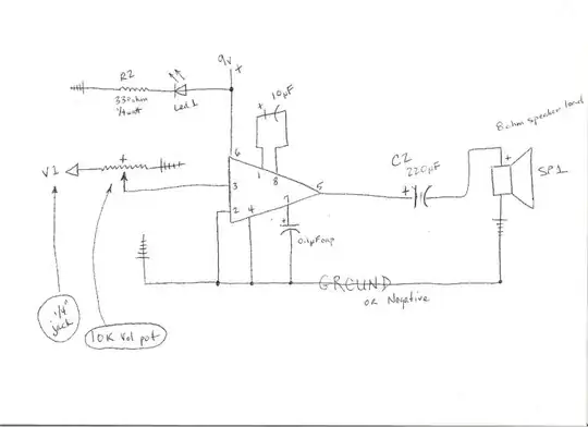
This is my first attempt at making a really simple audio amplifier. The schematics are below:-

200 Gain audio amp schematic

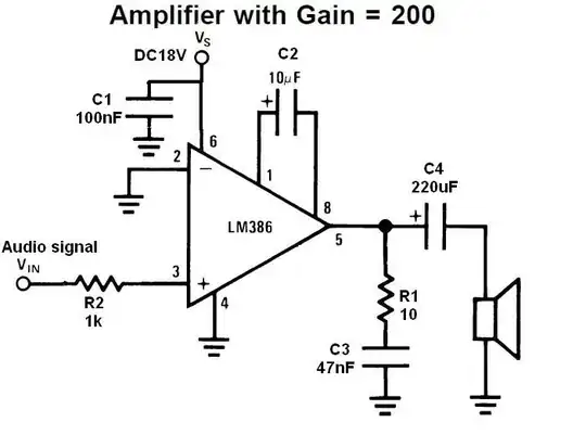
First I tried connecting the circuit to a 9V battery. (Multimeter reads around 8.3 Volts, which is in the operating voltage range of the LM386 as per datasheet) The result I have is lots of noise, sometimes cracks and pops and a barely audible sound of the audio input (it feels like highly attenuated form of input which is very bad). It doesn't even sound at least equal to the input! I want the gain to be around 200, so I do have a 10\$\mu\$F capacitor across pins 1 and 8 of the LM386.

I've also tried connecting to a 9.6V - 250mA rated unregulated DC adapter. The results are almost the same... (though I seem to get a higher voltage here..)

Initially I simply used a in-ear earphone to pick up the mono output. I also tried connecting a small speaker (pictured). It's apparently a 0.2W 8\$\Omega\$ speaker. The output is low, but the end result is similar to the earphone output..

Here's a snap of the breadboard.. Sorry for the bad quality pic. This config used the DC adapter and a 0.2W 40\$\Omega\$ speaker. I even checked all parts for continuity using a multimeter. I'm also open to tips on troubleshooting this, since I'm new. Breadboard snapshot

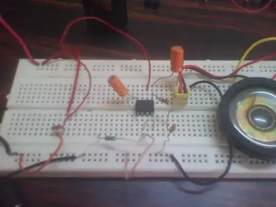
Top bus is the Vs and the bottom bus is the common ground. Input audio is connected to the left end of the 'green' 1k resistor. Its a very thin wire since its from a small 3.5mm TRS cable.

I don't want anything super loud, just audible maybe like 2x of the input signal. If so, what kinds of speakers would this amp be capable of driving? What would I need to make it sound acceptable? Basically, what's wrong with this circuit?


UPDATE: I followed all of your suggestions and my setup now consists of an additional 100\$\mu F\$ capacitor in parallel to the power, a 100nF capacitor in series to the input audio signal and a 10\$\mu F\$ capacitor connected to the bypass pin. There was a problem though, the 9.6V unregulated adapter I use seems to show 22 Volts on the power rails (under load).. this seemed to make the LM386 run really loud. I seem to hear the amplified audio at times when I nudge some parts here, but anyhow after sometime, the IC got too hot and so did the 100\$\mu F\$ capacitor at the power supply.

Updated schematic design

I can't really tell if it's all because of a bad quality adapter or the IC or breadboard or capacitors.. The capacitors were salvaged from an old PCB board of another circuit. Also since I think the last LM386 got fried, I desoldered another LM386 from another board and I'm keeping it in stock. This is the last 386 I have in hand now and I don't wanna screw this up.

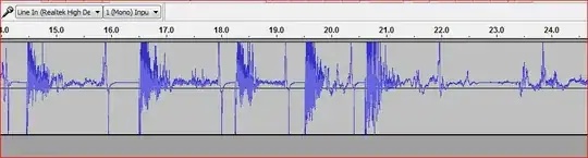
Now for safe testing, I drew power from laptop USB (5V regulated).. the volt at pin 6 of the new 386 shows a solid 5V. Speakers were really quiet so I hooked this up to an AUX cable and listened to it.. The output is weird and not satisfactory.. The sound seemed to be amplified when I nudge the power cable at pin 6 (ie, peaks of loud sound happens only at the beginning and then it fades to a point; see attached image/sound of the Line in recording)

(Using no cap at pin 1 and 8) Waveform spikes Sound Clip


UPDATE-2: I seriously doubt the volume level output of this amp.. through the speakers, I don't think it plays it loud enough.. the signal sounds sort of 'amplified', but the speaker doesn't seem to output it loud. Btw, I tried 9V batteries, 9V battery with 5V DC, 7.8V DC, 5V DC all sound the same. Is it because of my speakers? Also thanks to everyone who suggested adding extra caps to the power rails.. that part really helped in filtering a lot of noise. I used a 10\$\mu\$F cap there along with the 100nF cap. Or does adding more caps cause power loss or something?
Irfan
  • 237
  • 1
  • 4
  • 13
  • 1. The circuit says you should use 18V (it probably will work with 9V as well though). 2. Does the IC get hot? –  Apr 13 '13 at 07:13
  • @CamilStaps Yeah but the datasheet says the LM386 has a wide operating range of 4V - 12V (some say it can run on 5V-18V). The IC doesn't get hot at all! – Irfan Apr 13 '13 at 07:15
  • Whilst the LM386 might be able to handle 9V, the _circuit_ might be specifically for 18V ;) but probably not. Other question: if I see it correctly, you connected a _100_R to pin 5 instead of a _10_R one. You should have brown-black-black. Then also check R2, that should be brown-black-red. –  Apr 13 '13 at 07:18
  • @CamilStaps It's 10\$\Omega\$ resistor itself. It is brown black black and I also double checked using the multimeter. Similarly, R2 is also correct. – Irfan Apr 13 '13 at 07:25
  • Okay then! The only thing I can think of right now is to check if all grounds are connected. Some breadboards don't connect the whole lanes. So try a continuity check from the most left to the most right ground connection. –  Apr 13 '13 at 07:29
  • Is your audio input AC-coupled or DC coupled? What is the input signal average voltage, if you can check? (i.e. midway between positive and negative peak) – Anindo Ghosh Apr 13 '13 at 07:33
  • @AnindoGhosh I directly connected the input from a 3.5mm source, in this case, a mobile phone at 100% volume. (5mV rough average I think.. (using multimeter at one channel of the audio plug and checking DC values at 200m range) ) – Irfan Apr 13 '13 at 08:10
  • 1
    I am not a audio specialist, but shouldn't you have a series cap to block dc between the audio in and the R2/PIN 3 of the LM386? 0.1 ~ 0.4 uf caps are fine. – Passerby Apr 13 '13 at 08:42
  • The "lots of noise" problem will not go away with the 386. – Kaz Apr 13 '13 at 16:29
  • @Kaz I kind of figured.. Btw, I actually meant **only** noise. Right now, this is not giving anything but noise! The input signal is only barely heard between that. I don't necessarily want a high quality output, but it would be preferable anyhow. – Irfan Apr 13 '13 at 16:32
  • @Passerby This one isn't fresh. The one I had before was fresh that was bought from a local store and It was named 'D386' but I guess it's the same thing. This one is labelled LM386N-3 – Irfan Apr 16 '13 at 11:59
  • @Passerby Nope this isn't the one that has run on 20+ Volts.. I'm playing safe on this one. Not letting anything above 5V – Irfan Apr 16 '13 at 12:26
  • @Power-Inside I think I have a 386. I'll wire it up in your configurations to see if it works. Also, what about your caps? Are any of them limited to under 20V? You might have damaged some of them with the 20V. – Passerby Apr 16 '13 at 12:35
  • Not sure about the smaller ceramic disc caps ratings.. two of the electrolytic caps are rated at 16 Volts.. one of them is rated at 63V. I can hear output from the 220\$\mu\$F cap near the output. None of the caps are blown. Like I said, only the 100\$\mu\$F cap near the power rails got really heated. I discarded it anyway and I'm using the circuit without it. – Irfan Apr 16 '13 at 12:41
  • 1
    Re updated part: Powering from +5V should be fine. Intermittent behavior, such as the one you get, may be caused by poor connection between some wire and the breadboard. Also, double-check if what you have assembled on the breadboard fully matches the schematic. I have some notes on a [LM386 amplifier](http://lowvoltage.wordpress.com/lm386-audio-amplifier/) build, if they can be of any help. Note that on the schematic I've used there's no input cap C1 and R2&C4 have changed places. – DimKo Apr 19 '13 at 13:22
  • @DimKo I checked your notes, they're really great. I also switched the R2 and C4. Without the input cap C1, all I get is really loud noise! I see you used 10k resistor instead of 1k in the input. That's the only thing left for me to try (I don't have it right now)... – Irfan Apr 20 '13 at 04:42
  • @Passerby Thanks. Can you report your findings? I've updated my question and right now I still doubt the output strength of my LM386.. how loud does this get on around 8-9Volts? How do I confirm this? – Irfan Apr 22 '13 at 07:11

7 Answers7

6

The LM386 amplifier's inputs are an internally biased differential pair, with common mode input range extending to the indicated ground, Vee, or actually 0.4 Volts below ground.

In order to not disturb this internal biasing, the input signal must be capacitively coupled (or perfectly ground-referenced) - a capacitor in series on the input line is needed.

Next, for a voltage gain of 200, the input signal peak to peak needs to be under 1/200 of the output voltage range of the amp. While I could not find this specified in a quick scan of the datasheet, if we assume 7 volts output voltage range with a 9 Volt supply, the input signal needs to be under 35 mV peak to peak, to avoid clipping the signal. Clipping would result in mild to severe distortion of the output - though this does not explain the complete lack of signal you find on output.

If the incoming signal is higher than this 35 mV P-P, a potentiometer as an attenuator on the input is suggested.

Once these fixes are done, please revert with results, so the answer can be added to if needed.

Anindo Ghosh
  • 50,188
  • 8
  • 103
  • 200
  • I figured the lack of a input cap would be an issue. – Passerby Apr 13 '13 at 09:02
  • 1
    @Passerby Yep, the datasheet and contained schematics for that part have been criticized a lot on some forums because of this and other issues: Many people tried the part without an input cap, and failed despite "following the book". Also, it's one of the more poorly made datasheets in National's work: It leaves out more parameters than it covers! The fact that ground-referenced inputs are expected, while it should be a major highlight, is missing in versions of the datasheet I have seen, barring perhaps one version. – Anindo Ghosh Apr 13 '13 at 09:06
  • I think it's because some designs expect the previous stage to have a dc blocking series cap at the output, so having another in series will lower the capacitance? The most up to date datasheet on TI's website shows that the AM radio amp typical application does have the Cc input capacitor, while the rest of the typical applications do not. – Passerby Apr 13 '13 at 10:04
  • Thanks.. I'll try adding a input capacitor in series to the input. Should the capacitor be a 0.1~0.4 \$\mu\$F capacitor? Anyway, I don't have it right now, so I'll report back with results after some time. Also, is potentiometer really necessary? Won't the mobile's volume control do the trick? (sorry for a stupid question) – Irfan Apr 13 '13 at 11:03
  • 3
    @Power-Inside A 0.1uf/100nf is a common bypass cap, you should be able to find them anywhere. As for the pot, it's to avoid clipping, you can easily just start with the volume control on your phone low, and move up as needed. – Passerby Apr 13 '13 at 11:16
  • BTW, Peak-to-Peak Output Voltage Swing vs Supply Voltage is on p.4 of the National's DS (upper right pic); AFAIR, for 9V Vcc and 8ohm load, it's 6Vp-p max –  Nov 30 '16 at 00:27
4

A LM386 amplifier may behave quite erratically on a breadboard. Here are some ideas that may help you:

  • Start out with 20x amplification, i.e. without the capacitor between pin 1 and pin 8. Once you get proper sound at the output, you can always pump up the gain
  • Add a 10uF capacitor between pin 7 ("Bypass") and ground. The capacitor's negative lead is towards ground. "A small electrolytic or tantalum cap of a few uF from pin 7 to ground will isolate the high gain input stage of the LM386 from power supply noise, hum, transients, etc." (source)
  • Add a 100uF capacitor across the power supply rails, in addition to the 100nF capacitor you have. Some extra filtering never hurts
  • Keep all components as close to the LM386 chip as possible
  • Keep the input path as short as possible, to avoid external interferences
DimKo
  • 1,110
  • 8
  • 7
  • Thanks. Do I add the extra 100\$\mu\$F capacitor in series to my existing 100\$\mu\$F capacitor or parallel to the power source? – Irfan Apr 13 '13 at 12:57
  • Not in series, but in parallel with the existing one. Both of them should be across the power supply rails: one lead connected to V_s, one lead connected to GND. Also, mind the polarity of the electrolytic 100uF cap - the negative lead should be towards GND. – DimKo Apr 13 '13 at 13:06
  • The existing one is 100μF (micro-farad)?! It's shown as 100nF (nano-farad) in the schematic and looks like a 100nF in size, on the photo. Anyway, the idea is to have them both - one 100nF (smallish, usually ceramic) and one 100uF (larger, electrolytic). Their purpose is to filter different frequencies of noise over the power supply lines. – DimKo Apr 13 '13 at 13:16
  • Yeah sorry, my bad.. I thought you mentioned the electrolytic cap was nF.. My eyes are getting weak probably.. – Irfan Apr 13 '13 at 13:24
  • @Power-Inside A tantalum cap with no polarity? Tantalum capacitors are electrolytics, they have a polarity. The positive terminal should be marked, perhaps with a tiny black line along the side. If you have connected the tantalum capacitor the wrong way around, it is probably a write-off. – Anindo Ghosh Apr 16 '13 at 06:53
  • @AnindoGhosh I mistook them for ceramic disc caps. I don't have any tantalum caps. – Irfan Apr 16 '13 at 12:34
0

Try removing the capacitor between pins 1 and 8, you say that you want x2 output and you are using x200. Remove it so you have x20, next connect an audio device and set it to it's LOWEST volume and increase it slowly.

You may also try to add a trimmer between pin 3 and ground and connect the center pin to audio device to attenuate input signal, but do not remove the input capactor.

PeterJ
  • 17,131
  • 37
  • 56
  • 91
teo
  • 1
0

Try the following: 9 volts through on/off switch to pin 6, 16 or 25 volt 10uF electrolytic capacitor between pin 1 & 8 (positive to 1, negative to 8), a 0.01uF ceramic capacitor from pin 7 to ground, and a 16 to 25 volt 220uF electrolytic capacitor from pin 5 to an 8 ohm speaker (positive of cap to 5, negative to speaker positive). Pins 2 & 4 to ground, and all other ground terminals (jack input, power, speaker, volume potentiometer, etc). I have made many LM386 amplifiers for guitars, and the sound is great. The max output is 325mA...nearly 3/8 watt. The battery can be a standard 9 volt, or for longer lasting power, use a harness that holds 6 AA 1.5 volt batteries. An LED power-on indicator light can be added too.

enter image description here

0

The first diagram you posted had no 10 uF cap from pin 7 to ground. This is a must.

The Zobel network R2 and C4 must also be installed if you are using the LM386 as an amplifier. If you are using it as a part of an oscillator circuit then those two components are unnecessary.

There are a number of versions of the LM386 IC and lot of suppliers only offer the N1 version. This version has a reputation for being noisy and unstable, whereas the N4 version has a much better reputation in terms of low noise and stability. Hope this helps.

Austin
  • 1
0

I had the same problem, you need to increase the output capacitor for the speaker, 220 uF is way too small, I am currently running 2200 uF, there is a lot more noise, but the output is a lot louder, two 470 uF capacitors is probably best.

Yuri
  • 1
-2

This needs too much components. I tried this without connecting any component with pin 1,2,3,4,6,7,8 and it works properly and have a great sound without any internal noise. Actually, we make amplifier using only one capacitor ranges (100-220uf) or may more with pin 5 but that type of circuit have too much noise, to remove this easy way that use 104 nf ceramic capacitor and 10kohm resistence are in series and the end of capacitor is attached to pin 5 and the end of the resistence is to ground. 100% surely that it works without any internal noise.