0

There's LVC16374, it has 16 output pins. In one configuration I need 3 DACs 5 bits wide each, in another configuration I need 2 DACs 7 and 8 bits. I use R2R circuits for DACs.

I was hoping here's a prior art connecting more than one R2R DACs to same pins. Nope. Used LTSpice to simulate. R=1.5k. And I do not see any material difference in the output, while was expecting one ladder to affect another.

enter image description here

Is it a valid configuration? What do I overlook? It is clear simulation is not a real life, but I expected to see something at the millivolt level even in ideal life...

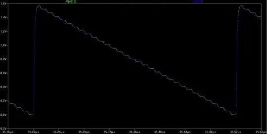
Edit: after setting voltage source properties to the 10 pF parallel resistance and 130 Ohm (3.3V/24mA) series resistance I have got the following graphs:

enter image description here

enter image description here

and now I am not sure if it is good idea to use this circuit as a video DAC.
Anonymous
  • 6,908
  • 1
  • 14
  • 41
  • 2
    Are you simulated voltage sources ideal? If so, why do you think they would affect each other in the sim? – brhans Feb 13 '23 at 20:39
  • @brhans Agreed... Parallel capacitance is in the datasheet (7pf + board/conductor capacitance), but have no idea what to use for series resistance. How to identify it properly? – Anonymous Feb 13 '23 at 21:11
  • https://www.ti.com/lit/an/scba011/scba011.pdf on page 16 shows "simplified LVC output circuitry" without any resistance... – Anonymous Feb 13 '23 at 21:27
  • Ok, given its output is 24 mA and voltage is 3.3 V, let's take 130 Ohms... And use 10 pF as parallel capacitance. – Anonymous Feb 13 '23 at 21:33
  • Wrong page. It's page 20. But it doesn't matter...the point is that the MOSFETs have an equivalent resistance. Your model for the resistance as 3.3V/24mA=130Ω is very poor and unrealistic. TI provides an IBIS model for this part. You can get accurate results by interfacing this model directly into your SPICE simulations. However, it sounds like you can just get by with a voltage source + series resistance model, but use the data in the IBIS model to calculate that resistance. See my answer here on how to do that: https://electronics.stackexchange.com/a/573907/254890 – Ste Kulov Feb 14 '23 at 12:40
  • Sorry, I meant it's PDF page 20...which is labeled page 16 at the bottom of the physical page. That's why I was confused and took me a while to find. Anyway, it's Figure 14 I believe you were referring to. – Ste Kulov Feb 14 '23 at 12:47

0 Answers0