7

I'm building an analog distortion effect for my guitar. During testing I measured a random 470 kHz signal with an amplitude of 500 mV. Where does this signal come from, and how do I get rid of it?

I designed a op-amp circuit/PCB with a USB-C port for power, a boost converter (LMR62014XMF), and a linear regulator (TLV767) to provide a stable 8 V power source.

power supply circuit

The input stage is a voltage follower circuit just for impedance conversion.

Voltage follower circuit

After the input stage (TP9) I measured the random 470 kHz signal with an amplitude of 500 mV. Over the next stages the signal gets amplified and I end up with up to 3 V at the output.

frequency spectrum

signal in time domain

If I touch a GND connection of the circuit the signal becomes weaker. If I also touch another grounded element like my laptop the signal disappears completely.

I also observed the following: The circuit has a switch which connects the output AUX plug either to the output of the circuit (ON) or to the input AUX plug (and therefore to the input of the circuit as well) (OFF); the circuit output is left floating. The signal only appears when the switch is ON.

I would appreciate any ideas or suggestions about where this signal is coming from, and how I could fix it.

Edit:

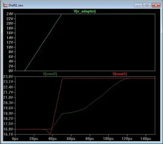
As some suggested, the boost converter might be the problem. I will attach some measurements of the supply voltage. Both measurements where captured using AC coupling.

The switching frequency of the boost converter should be 1.6 MHz and allow a switch current of up to 1.4 A. The LDOs max. current is 1 A. The complete circuit draws only about 12mA.

9 V boost converter output: boost converter output voltage

8 V LDO output: LDO output voltage

Edit 2: As requested I will add pictures of the complete circuit as well as an image of the PCB layout.

Main Effect circuit (Distortion + Treble) main effect circuit

Gain Stage gain stage

Complete Power Supply power supply circuit

IO - USB-C, AUX in/out, 9V Barrel Jack (Alternative to USB-C) io circuits

PCB Layout:

4 Layer PCB. Ground zone on the back layer. 8V zone (and small 9V zone in the top left corner) on the first inner layer. 4V zone on the second inner layer

pcb layout

Edit 3:

Open-Loop Gain and Phase of the TL081 Open-Loop Gain and Phase of the TL081

Solution:

After some comments/answers mentioning instability I took some more measurements which verified that this is indeed the source of my problem.

The easy solution for my prototype was to add a miller compensation to the tone and gain stage. For the next revision I will try to find the source of the Instability to eliminate it completely. Thank you all for the solutions, ideas and explanations. I learned a lot.

PS: The whole project can be found on GitHub, but I will of course also provide more pictures and measurements if needed.

Lukas
  • 73
  • 5
  • 1
    The boost converter is a suspect here. Does the frequency change if you load down the boost converter a bit? – Hearth Feb 07 '23 at 16:39
  • @Hearth What do you mean with load down? – Lukas Feb 07 '23 at 16:53
  • @Hearth Yes, that was my thought as well. Does the signal change if you move the input stage away from the PSU? Can you look at the boost converter with your oscilloscope and see if it too is running at 470kHz? If the worst comes to the worst, can you incorporate a low pass filter that would kill the signal? After all it's a good 20 times the highest frequency you are likely to be interested in. A 3K3 resistor plus a 1nF capacitor low pass RC stage has a cut off frequency of about 48kHz – Peter Jennings Feb 07 '23 at 17:00
  • @PeterJennings I updated my question with some measurements of the supply voltage. The boost converter should run at 1.6MHz. Using a low pass could be a solution but I really want to know where the signal is coming from in order to prevent any further issues caused by the same problem. – Lukas Feb 07 '23 at 17:19
  • 1
    I suspect that the signal is external. Perhaps from within the laptop. The shield of the USB cable should be connected to laptop ground, but some say not to your circuit ground. Since touching the laptop clears the signal, the problem seems related to interconnect cabling. – RussellH Feb 07 '23 at 17:53
  • @RussellH For all above measurements the USB cable was not connected to the laptop. But after your comment I tried it with the USB cable connected to my laptop and the signal disappeared. – Lukas Feb 07 '23 at 18:13
  • Try a small ceramic, high-voltage cap from circuit ground to chassis ground. – rdtsc Feb 07 '23 at 18:22
  • @Lukas: You should post the rest of the circuit. We can’t see what is loading TP9. I need to see how the 4V midpoint bias is generated and distributed. – RussellH Feb 07 '23 at 19:06
  • @Lukas to "load down" a power supply is to make it supply more current, to put a heavier load on it. My suggestion was to put a resistor, or some other load, between the boost converter output and ground. If the boost converter was the source of the noise, since the noise isn't a harmonic of the switching frequency, my theory was that it was a harmonic of the burst frequency of a converter running in burst mode (a higher-efficiency, but noisier, mode of operation for low currents that most modern controllers support). – Hearth Feb 07 '23 at 20:24
  • @RussellH Yeah I tried to keep the question short. I added pictures of the complete circuit. – Lukas Feb 07 '23 at 20:31
  • @Hearth Ah okay thank you for the explanation. I did not know that term. – Lukas Feb 07 '23 at 20:34
  • @Lukas: Where does GAIN_in connect to? The schematic shows an extremely hig gain stage with Ri=0. – RussellH Feb 08 '23 at 03:28
  • @RussellH gain_in is connected to effect_out. So Ri is R2 – Lukas Feb 08 '23 at 09:06
  • Is TL081 unity gain stable? – winny Feb 08 '23 at 10:47
  • @winny I took a look at the datasheet and as far as I can tell the TL081 should be unity gain stable. (I added the [Open-Loop Gain and Phase diagram](https://i.stack.imgur.com/4x0rK.png) to the question if you want to take a look) – Lukas Feb 08 '23 at 20:47
  • 1
    Have you zoomed in on the scope to be sure it's really 450 kHz and not an undersampled higher frequency signal of (say) 100 MHz or 1.4 MHz? – tomnexus Feb 08 '23 at 21:10
  • @Lukas Good. Would be low hanging fruit if it was as simple as an oscillating opamp. – winny Feb 08 '23 at 21:39

3 Answers3

2

You should move "U1" and it components, everything between C3 and C11, the boost converter to a different ground plane and not mix in between the rest.

You need to study a bit about "Star ground", you don't want "digital" and analog stuff mixed or close to each other. the need to be separated.

Maybe even using a "bead" between C11 and C1, the linear voltage regulator.

Use an additional opamp to split the power rail and create virtual ground, like done guitar pedals.

NaturalDemon
  • 307
  • 1
  • 8
2

My suspicion is that your circuit oscillates. It could also be the switcher as others suggest. These issues are not mutually exclusive.

The root problem may well be your 4V midpoint, which I suspect is not low enough impedance enough for all the stages which use it as a reference. When its impedance is not low enough, it becomes an unintentional feedback path across multiple stages.

I don't see any component values in your fuzz stage but these stages do typically have a fair bit of gain. Same for the tone stage that comes after. So you quite likely have gain plus unintentional feedback which easily equals oscillation. You might have pickup on top of, or triggering, that oscillation.

I also don't see any rolloff caps across the feedback resistors of those two stages, which are always advisable (you can provide for them, you don't have to fit them - usually you can't tell for sure until you test your prototype.)

The best way to figure this out is to disconnect your power circuit and run the whole thing from a clean power source, a linear bench PSU if you have one, if not:

  • start with a pair of 9V batteries giving a proper split supply (now you know there is no issue with your 4V reference.
  • then try a single 9V battery and get the 4V reference working OK - you might need to use another opamp stage to buffer the 4V, or one of the many mid-rail reference ICs available.

When all this is good, try powering it from the 5V/switcher circuit.

I don't think that there is any way for anyone to really tell you if this is oscillation or noise pickup or a combination of both without working through things logically like this. (Of course you can look at switcher noise on one channel of a scope and the spurious signal with the other, that will tell you if they are related, but even then that doesn't mean that your 4V ref is not an issue or that you do not have an oscillation problem.)

Other stuff:

  1. your output after the decoupling cap needs something like a 10k resistor to 0V so it doesn't float if the receiver circuit is also DC blocked.
  2. R2 needs to be physically as close to U3 as possible - that input is a virtual earth, and it will pick up noise like anything. It doesn't look too bad on your layout but best is to place the input resistor to an inverting opamp as close to the pin as possible.
  3. the whole business about touching grounds and things changing is also suspicious - unfortunately with most laptops being floating anyway, it's all a bit of a guessing game. Best bet is to get things working under known, properly grounded, conditions, and then go step by step fixing issues as you go. It really can be very tricky, so really go one step at a time.
danmcb
  • 6,009
  • 14
  • 29
1

I see four places where there could be problems.

The circuit has a switch --- the circuit output is left floating. The signal only appears when the switch is ON.

  1. Capacitor C8 is floating when the switch is in AUX position. Place a resistor between gain_out and circuit ground. Make it as small as possible without affecting circuit performance. This is a longshot in solving the oscillation, but the capacitor bias should be properly maintained anyway.

  2. The TL081 is a high performance amplifier. The input capacitance is only a few picofarads. Its bandwidth will easily accommodate 470kHz. A ground plane under his chip (especially under the input pins) can introduce instability by increasing this capacitance. Place a keep-out directive under the op-amp in the PCB editor. Adding a feed back capacitor from the output to the inverting input (Miller compensation) is usually used to prevent instability. 10 to 100 pF is often enough. U2 is particularly high gain, so placing a Miller capacitor here may solve the problem. Place a Miller cap across the other amps in the chain as well.

@danmcb has mentioned these as roll-off caps. From this point of view set a roll-off corner at about 50kHz. This then should take care of Miller compensation as well.

  1. @danmcb also mentioned the midpoint bias distribution as a possible problem. I agree. I am not a big fan of distributing midpoint bias. The red and yellow lines in the image below indicate why. They indicate two positive feedback paths both use the midpoint bias path to close the loops.

At 470kHz, the skin effect raises the resistance of the copper wires. The 33uF bias filter may not be close enough to filter properly. It may be beyond its self resonant frequency although if ceramic probably not, but check anyway.

Buffering the midpoint voltage divider with a unity gain op-amp will provide a good dc bias point, but may not solve the problem for ac because even if the voltage is constant, it must sink and source high-frequency currents while maintaining a constant voltage.

The solution that works for me is to provide a local mid point bias for each op-amp.

enter image description here

The region circled by the blue line does not provide good balance to the midpoint reference. This can produce a common mode conversion to differential mode. The high gain of this stage may then overcome the losses throughout the positive feedback loops.

  1. It is crucial that a midpoint bias distribution network be low impedance and provide an ac ground as well. Let me demonstrate with a circuit diagram:

schematic

simulate this circuit – Schematic created using CircuitLab

The circuit on the left is a standard split supply arrangement. Converting to the single supply on the right lifts the midpoint bias from our nice clean ground and leaves it floating for both ac and dc. Notice that all the decoupling capacitors are still there in the same configuration. The capacitors that decoupled the negative rail, now decouple the midpoint bias. Most folks leave these off when converting to single supply, but they are still necessary.

The capacitors decoupling the positive rail need to be connected to the new ground because the midpoint bias is compromised.

The red arrows on the right indicate a positive feedback path. Mostly the gain around the path is less than 1, but if it isn't the circuit will oscillate. The path always existed but the battery from mid point to negative makes the gain a loss.

The wiring must be exceptional to avoid coupling between stages. A suggested method is to use a local midpoint bias for each op-amp. The will eliminate the positive feedback loop entirely.

schematic

simulate this circuit

For the complicated input circuit of U2 a buffered voltage divider would be good. Use a TL082 (Dual TL081). The second amplifier is used as a unity gain buffer as below:

schematic

simulate this circuit

Any one of these suggestions (or a combination) could clear the oscillation. The external ground is reducing the gain of a non-inverting closed loop of some kind, two of which I have indicated above. I have not looked for others that could occur through poor layout. So my suggestions may not work but they are improvements.

RussellH
  • 12,496
  • 2
  • 9
  • 34
  • Thank you for your detailed answer/explanation. Would I be able to verify, if the midpoint bias is the the source of the problem by measuring? As far as I understand I would measure the same noise on the 4V reference in this case. – Lukas Feb 13 '23 at 11:18
  • Probably not. DMMs don’t have the bandwidth. Oscilloscopes will introduce an external earth connection that seems to stop the oscillation. – RussellH Feb 13 '23 at 14:04