Consider this circuit:
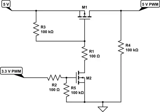
simulate this circuit – Schematic created using CircuitLab
Ignoring the different threshold voltage, the (time domain) simulation shows a clear difference between Q1 and Q2. In particular, it takes about 300ms for K1 to go from "fully off" to (almost) "fully on" (and the current continues to rise slightly for some time after that), whereas K2 takes only about 60ms. In other words, Q1 has a very long rise time and could be said to "switch slowly", while Q2 "switches quickly" (at least compared to Q1).
I know relays don't like being turned off slowly (contact arcing), and I suspect being turned on slowly isn't much better. (Note that the turn-on time for the relay itself is on the order of 5-10ms.) Therefore, it seems reasonable(?) that I would rather use Q2 than Q1 for this application.
Questions
- Why is there such a significant difference between Q1 and Q2? Given only a data sheet, how would I go about estimating whether some other MOSFET is likely to act more like Q1 or Q2? What would I look for when selecting a MOSFET in order to get a shorter rise time?
- I'm considering an FDP3682 in my actual application. Unfortunately, CircuitLab does not have a model for this component. Is there an easy way (without actually buying parts) to determine how an FDP3682 is likely to behave in this circuit?
Note: In my actual application, the gate input is driven by an RC delay, which I have approximated here by a sine function generator. (Naturally, this breaks down badly after the peak of the sine wave, but I'm only really interested in the behavior when the MOSFET switches 'on'.) The original version of this question shows the RC delay and includes additional context.
