1

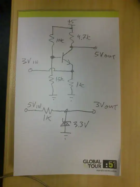
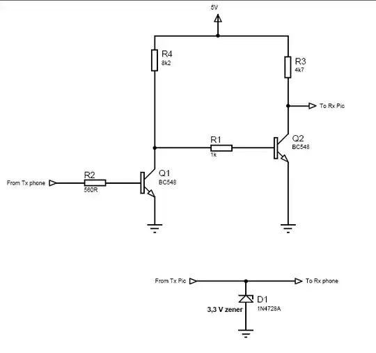
I have found this schematic and am confused about the transistor and the diode. I know that the phone voltage is around 3V and the PIC voltage is 5v, and it's a level shifting circuit.

Interfacing Phone with Microcontroller

My questions :

  1. Does the transistor have a value like resistor-ohm or like capacitor-farad? I know that it's NPN. Before this, I went to buy and said just NPN but they asking about the code (like BC548), but what if they don't have BC548? What else should I say besides NPN?
  2. Why using a zener with value 3.3V? How can I calculate that value?
DexDarrel
  • 35
  • 7
  • The PIC voltage is probably 3.3V, not 5. If there is voltage on the phone line, the zener will clip it to 3.3V, so that the PIC is not subject to an improper voltage. – Kaz Apr 11 '13 at 19:19
  • @Kaz I'm pretty sure the PIC is running in 5V in this circuit. Anyway I'm going to use AVR that running 5V, that's why I need to know about this circuit. – DexDarrel Apr 11 '13 at 19:55

4 Answers4

3

The PIC / AVR is not going to be happy driving a 3.3V Zener with its 5V output. Maybe consider the following level shifter instead:

markrages
  • 19,905
  • 7
  • 59
  • 96
  • thank you for the schematic. I'm recognized the transistor above is the same NPN. But how can I know which NPN one should I buy ? And I see that in circuit above there is only one transistor, does the output is [inverted](http://www.avrfreaks.net/index.php?name=PNphpBB2&file=viewtopic&p=576057) ? – DexDarrel Apr 12 '13 at 00:48
  • No it is not inverted. When 3Vin is low, the transistor in ON and 5Vout is also pulled low. And when 3Vin is high, the base-emitter voltage is bellow the threshold and the transistor is not conducting. thus 5Vout is pulled high by the 4k7 resistor. – Blup1980 Apr 12 '13 at 05:59
  • I got it now. thanks @Blup1980 and markrages – DexDarrel Apr 13 '13 at 15:33
2
  1. A transistor is a different type of (active) component entirely, to a passive component such as a resistor/capacitor/inductor. They have many different characteristics listed in the datasheet, one of the most important being current gain. If you don't understand much about them I suggest you get hold of a decent introductory electronics book and read up about them. There are thousands of part numbers, but in many cases you could use many different options. In a circuit such as this most general purpose NPN transistors will do (2N2222, 2N3904, BC337. etc)

  2. The zener appears to be used in order to ensure the voltage does not rise above 3.3V (the zener will start conducting above this voltage) thereby protecting the 3V phone input from overvoltage. You don't need to calculate this value, you simply need a 3.3V rated zener, of which there will be many part numbers to choose from (assuming this is what the circuit requires)

EDIT - regarding more detail on why the transistors can be swapped, it's hard to explain briefly. They do have similar specifications, and are available in the common and easy to use through hole TO-92 package. The circuit shown is not ideal, but for a rough shifting circuit it will probably work with some distortion (how well depends somewhat on the input signals DC bias level)
Since important parameters like current gain can vary widely with temperature and between parts of the same number, a good transistor circuit will not rely on these parameters but control them with some basic feedback (e.g. by using an emitter resistor in a common emitter circuit)
Any good electronics book will have a section on how to use a transistor, understand it's parameters and design a circuit that meets your specifications with them. The website All About Circuits is pretty good (see section 3 for semiconductors), and book wise this question and it's answers should be of use: Basic Electronics Book. With a few hours of reading and a couple of breadboard experiments you should begin to see things more clearly.

Oli Glaser
  • 54,990
  • 3
  • 76
  • 147
  • At least a simple explanation, from what you said : 2N222, 2N3904, BC337 etc. What are the same or common thing that makes those transistor will do the same as BC548 ? Are the same 'current gain' value ? – DexDarrel Apr 11 '13 at 19:40
  • @DexDarrel - I added a bit more to the answer, but it's hard to give a thorough treatment without going on a considerable length. I suggest doing some reading first, then try to build the circuit. If it doesn't work as expected, then ask another question (or update this one) and we can review the exact causes. It's all good learning even f a circuit doesn't work. Also, if you don't have an oscilloscope you should consider getting hold of one (I assume you have a multimeter) – Oli Glaser Apr 11 '13 at 20:52
  • Thank you for your answer. I am a software engineering student, so my hardware stuff are so minimal. I think i start getting it for now, and yes, I still need more reading. I will come back later if there are any issues. – DexDarrel Apr 12 '13 at 01:00
  • No problem - see the circuit @MarkRages posted, it's an improvement on the current one - it does not invert the signal as you ask. I'm not sure of the overall intent of your application, but also include the resistor with the Zener as shown if it is driven directly from the PIC pin - I had assumed it was RC filtered beforehand (i.e. PWM from the PIC -> low pass filter) – Oli Glaser Apr 12 '13 at 01:31
  • I'm doing a project that need to connect Microcontroller (AVR-ATmega8) and GSM Module (Old Sony Ericsson Phone -K508i) for sending TEXT/SMS. I'm new in electronics, as parts by parts still need more learning. Thanks again for the help. – DexDarrel Apr 13 '13 at 15:52
0

1: Take a look at the datasheet for the transistor Try to find something that is close to it. If you can not find one at a local store, take a look at mouser or digikey.

2: The diode is a clamping diode.

Reid
  • 2,030
  • 1
  • 21
  • 38
  • I'm still practice in reading datasheet, but can you explain simply to me : What is the basic (value) so I can define 'something that is close to it' ? Is it the requiring collector current or ? – DexDarrel Apr 11 '13 at 19:49
  • There is no simple answer. All parameters that are important in the circuit at hand must match enough to keep the circuit working. That's the real answer, any others are simplifications that will often work because most circuits are not critical. – Wouter van Ooijen Apr 11 '13 at 21:21
0

For performance evaluation the most important parameters to me are usually: -

1) Beta or current gain

2) Ft or frequency that the current gain (beta) falls to unity i.e. it no longer amplifies

3) Current carrying capability i.e. can it switch or control a low impedance load

4) Voltage withstand i.e. can it switch or control a high voltage load

Next I would probably look at a few other things especially if i knew it was a hard-choice for the transistor but the above will do for now. (nb I nearly put in Cc and Pt)

For the type of job that your circuit requires the BC548 is a good general purpose transistor that can be used almost anywhere providing you check that the circuit it's intended to be used in won't expect too much given the four factors above (plus others but for beginners this is enough to take on-board).

If your PIC is ruinning at 5V then probably a 5V1 zener will be OK.

Andy aka
  • 434,556
  • 28
  • 351
  • 777
  • Thank you for the explanation. But why the zener 5v1 ? And not 3v3 ? As I know, the PIC driving 5v to Phone that just need 3v (or maybe a wrong understanding by me) – DexDarrel Apr 13 '13 at 15:50