1

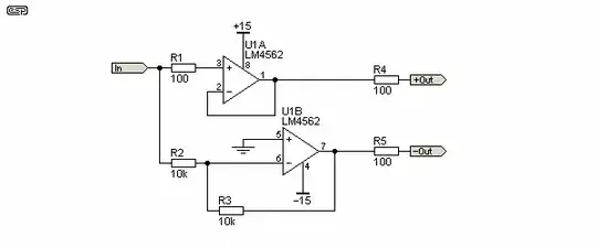
This diagram:

Balanced line driver

shows an output stage that can be used to drive balanced lines. Here, it is used on a piece of audio equipment and connected to an XLR jack.

However, I want to make this "idiot-proof". If this is connected to a mixer and someone accidentally switches on phantom power, I'm afraid that this might fry the opamps on this stage. How would I go about implementing this type of protection? (The piece of equipment that I am designing is not phantom-powered; it's powered off the mains.)

My initial idea is to insert capacitors (10 μF bipolar electrolytic) between the opamps' outputs and the output resistors (R4 and R5, which are to prevent oscillation) and then put a pair of back-to-back Zener diodes between the opamps' outputs and signal ground. Would this work?
El Ectric
  • 225
  • 3
  • 16
  • 1
    The next question is, what does phantom power mean to you? 48V bias via 6.8 kohm resistors? If op-amp drives 0V to output, it's only 7 mA. Can't the op-amp handle 7mA without protection? – Justme Jan 31 '23 at 18:15

1 Answers1

2

That will likely work.

What you really want to protect against is a charged coupling cap at the phantom supply side dumping into the opamp (and the base-emitter junction of the preamp at the supply side), with 100R build out resistors you are clamping that to a maximum of 480mA, 520mA with worst case (52V) phantom.

Usually I just do a reasonably serious diode from each supply rail to each opamp output behind the resistors to divert the current pulse, and make sure my supply bulk caps are large enough to avoid significant bus pumping with realistic values of P48 output coupling caps.

Here is a paper discussing some of the issues from the other end of the cable, but the things sort of translate.

https://thatcorp.com/datashts/AES7909_48V_Phantom_Menace_Returns.pdf

Dan Mills
  • 17,266
  • 1
  • 20
  • 38