6

I am working with a MC33186DH1 5A H-bridge IC.

It seems to simplify things quite a lot. The data sheet shows this simple schematic:

Page with module

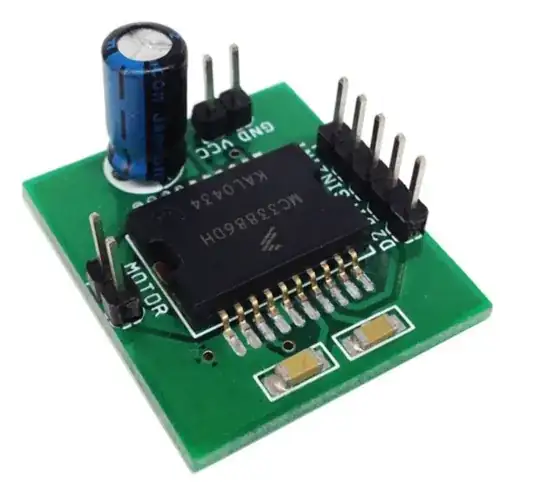
I found a break out board that mostly follows that design:

enter image description here

My concern is that this simple approach following the datasheet seems to be an outlier with every other board I can find adding four SK diodes to the output. I have no idea what they are doing but assume they make it more robust somehow.

Example 1:

enter image description here

enter image description here

My first though at seeing four diodes was "full bridge rectifier." Perhaps it is on the input so it works regardless of battery polarity, but with almost every other board doing the same thing and dual H-bridge modules having four diodes each it just doesn't make sense.

enter image description here

I am hoping there is someone smarter than me or who has seen this with some otherHh-bridge setup that can explain what they do.

JRE
  • 67,678
  • 8
  • 104
  • 179
AndrewT
  • 263
  • 1
  • 9

2 Answers2

11

Without clearly seeing the part numbers on the diodes, I would assume they are Schottky diodes such as the SMT version of 1N5819 (1A diodes), maybe this one marked B14.

They would end up in parallel with the body diodes of the internal MOSFETs in the driver chip, so would result in the chip running cooler (body diodes drop more voltage, are slower, and are actually on the chip so the energy lost has to be dissipated as heat from the same chip doing the switching).

Connection wise, think of them from either end of the motor coil to each supply rail.

Both schemes will work, the one with the Schottky diodes is better, depending on the supply voltage vs. motor voltage and the switching frequency (and the added cost is pennies).

enter image description here

Spehro Pefhany
  • 376,485
  • 21
  • 320
  • 842
  • 1
    Thanks for the explanation, the diagram was especially helpful also. So if following this approach means less heat for the cost of 4 diodes then why not. Thank you – AndrewT Jan 31 '23 at 01:11
  • 3
    an exquisite job on the hand-drawn diagram extension, @Spehro Pefhany , not unlike the legendary [Freehand Circles](https://meta.stackexchange.com/questions/19478/the-many-memes-of-meta/19775#19775) :) – spamove Jan 31 '23 at 09:16
  • 4
    Wow, much diagram, so wobble, many amaze. – RedGrittyBrick Jan 31 '23 at 10:26
  • 2
    @RedGrittyBrick Trackballs are not ideal for drawing straight lines, kind of the reverse of the "Etch A Sketch" issue. – Spehro Pefhany Jan 31 '23 at 10:30
  • 2
    Please don't worry about it. Seeing such an esteemed and valued contributor make such ultra lo-fi yet still intelligible diagrams somehow makes me happy. – RedGrittyBrick Jan 31 '23 at 10:40
  • A work of art! They actually do form a full bridge rectifier but that seems coincidental, and it looks like it's reverse-biased. Could it be anything to do with shorting away back EMF? – Greenaum Jan 31 '23 at 11:35
  • @Greenaum Yes, if one of the half-bridges is turned completely off when current is flowing through the coil, then one or the other diode on that side will conduct briefly. – Spehro Pefhany Jan 31 '23 at 11:40
  • @SpehroPefhany It's just something I was taught at school, if you have a relay or a motor or any sort of decent-size coil, you put a reverse-biased diode across it, to save other components from dealing with large reverse voltages. Not all coils, of course, but where appropriate. Since this motor can be powered in either direction, presumably that's why there's four diodes. – Greenaum Jan 31 '23 at 12:27
  • @Greenaum Yes. You have to be a little careful with this configuration because it's possible to pump energy into the the power supply and cause it to go over-voltage (think of a boost converter). – Spehro Pefhany Jan 31 '23 at 12:42
11

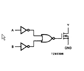
The datasheet MC33186DH1 shows body diodes on the output MOSFETs:
Block diagram

On page 7, "freewheeling diode" voltage and speed are given: 2V at 3A, and max 5µs recovery (albeit at a paltry 4A/µs current rate; maybe this rate is typical of the device's switching speed into a short circuit?).

Even if switching is synchronous, due to the mismatched delay times between devices (dead time is not specified, and not well indicated; only Fig. 22 I think hints at it), significant power can be dissipated during that brief gap, in which case schottky diodes can reduce it, at the expense of added components, and usually some additional losses due to their capacitance.

Typical candidates would include B140 to B340, PMEG4020, etc. Most schottky types aren't very picky by the way; there are largely two types, one optimized for slightly lower VF at expense of higher leakage (which can be a problem at high operating temperature (≫100°C), where leakage rises so high it dissipates excess power and runaway failure occurs; so, avoid that situation). Even the ancient 1N5819 still has comparable characteristics today.

Connection will be in parallel with the freewheeling/body diodes. See this example from the old ST L297 stepper controller datasheet:
schematic

And yes, they had a whole chipset put together; ah, how times have changed, all of that and more is integrated nowadays.

L6210 was in fact a monolithic schottky array, but you can use single or dual or whatever parts as you like with suitable ratings.

Note that, as long as switching is synchronous, the diode dissipation will not be very much, but at least some minimum size (ampere rating) is required, otherwise the voltage drop is too high and significant current will flow into the body diodes, incurring recovery losses again. I would keep ratings to the 1-3A, 30-60V range (voltage rating of course dependent on your supply range).

Speaking of old things, MC33186 itself is rather old. You may consider using a newer device, which won't suffer from these issues (slow switching, recovery losses [or as much], smaller footprint, etc.).
Tim Williams
  • 22,874
  • 1
  • 20
  • 71