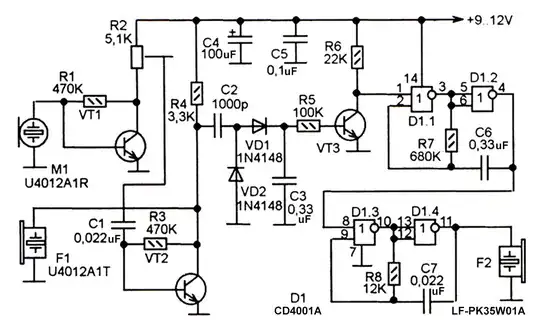
 This is a simple sonar device using piezoelectric mic and speaker. I understand, the C2-VD1-VD2-C3 is detector circuit that is intended to enable the sound generator based on CD4001 that produces sound tone once an obstacle is detected.
I don't understand the purpose of the VD2 though. It looks like the idea was to implement a voltage doubler, however, for that to work we need to feed AC to it, and AC is not present there, so, as far as I understand, there is no chance for VD2 to become forward biased. In my opinion, a single VD1 and C3 would suffice. (w/o C2 too).
Why is VD2 there?