1

I am trying to design a small PCB that I can use to turn on an output once it senses a voltage above a certain threshold

Usage - in a vehicle 12v in from battery, once it detects battery is charging (voltage over 13v) it then turns on an output. thus giving a simulated ignition live.

I'm thinking I could manage it with a NPN PNP and maybe a zener but not really sure how it should go together.

Can anyone advise a good solution using minimal components?

robbrown92
  • 177
  • 9
  • Are you saying that the switched output is open circuit when the incoming supply is below 13 volts and, when it is 13 volts or above, the switched output connects to the incoming supply line? Or, are you looking to (say) generate a logic level output that indicates the incoming supply is above the threshold? How accurate do you want it to be? What happens if on connecting the switched output to the incoming line, load current in the switched output causes the incoming supply to droop below 13 volts --> it might become an oscillator (why we use hysteresis) on under-voltage-lock-out systems. – Andy aka Jan 20 '23 at 15:10
  • thats correct I'm looking for it to provide a voltage sensesed switched live and then run through I assume a pnp mosfet – robbrown92 Jan 20 '23 at 15:14
  • You might want to read the full comment because I was editing it while you answered. – Andy aka Jan 20 '23 at 15:14
  • One comparator with built in reference and two resistors? – winny Jan 20 '23 at 15:16
  • Im thinking a comparator is the best bet, however a voltage monitoring IC may be a slightly more modern approach. though an LM741 should work and they are very cheap. I like the idea of using a microcontroller however not sure how i would program it and I'm going for as cheap as possible in terms of manufacture – robbrown92 Jan 20 '23 at 15:31
  • would the comparator work considering vcc would be 12v when ignition is off and vcc would be 13.4v when ignition is on, without a fixed voltage vcc – robbrown92 Jan 20 '23 at 15:44
  • Why are you going for "as cheap as possible"? If it's a one-off then, "cheap" is out of the window. If you are hoping to sell the design as a product then cost cutting can lead to substantial field failures and then you'd wish you'd spent a few more cents on the design. If going in a car then load dumping of up to 100 volts is a significant threat to a weak design BTW. – Andy aka Jan 20 '23 at 15:44
  • it doesnt have to be as cheap as possible I guess, I'm just looking for options and the main thing is keeping the component count down to keep the PCB as small as possible. An inverting comparator seems the best bet however if there is a suggestion for a microcontroller that perhaps is more efficient and can be controlled more accurately I'm open to it. I'm not an EE just a hobbyist – robbrown92 Jan 20 '23 at 15:48
  • [load dumping - be prepared](https://electronics.stackexchange.com/questions/204790/how-to-protect-audio-device-in-car-amplifier/204791#204791) – Andy aka Jan 20 '23 at 16:10
  • could i not use a Zener diode to protect from overvoltage? – robbrown92 Jan 20 '23 at 19:33
  • if i put a fuse on the batt input and then a 25v zener diode to gnd if it over volts it should short live to gnd and blow the fuse. From reading on the load dumps it sounds like it only happens when battery is disconnected outside of normal operation and would likely destroy many circuits in the vehicle – robbrown92 Jan 20 '23 at 19:35

3 Answers3

1

Given the bargain price of general purpose high-voltage (36V) comparator ICs that were designed in the 70s and are still made and sold, you could use a comparator with hysteresis, and a mosfet or relay as a switch.

A discrete transistor circuit can be designed to survive large transients without much protection, since you can use much higher voltage rated transistors than are feasible in a general purpose IC process.

Another approach is to use a voltage monitor chip fed from a voltage divider and a logic level mosfet as a switch. Voltage monitors have various delays and hysteresis built in and should be fairly robust. You can buy them in 3-pin TO package, so a basic solution can be just as simple as that using a comparator.

Another concern is idle current consumption. If the circuit is permanently connected to battery, then ideally it should consume “no” power until the voltage is above 12V. In practice even with a bare-bones discrete transistor design you can have it consume a micro amp when idle at room temperature. Make sure you check the power consumption when the whole thing is at 80C - a rather typical situation for car applications, or even 115C if used in the engine bay. Some diodes get quite leaky at such temperatures, so testing goes some way towards not getting to a dead battery after a car-free weekend :)

1

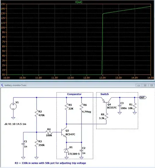
Here's a mostly discrete solution using a voltage reference and transistor as a comparator. It should draw very little current (under 100 uA) until it hits the turn on voltage. The sharpness of the turn on will depend on the load, if you need it to drive more than say 10 mA you might need to buffer it.

One downside is the cost of the voltage reference, the one shown can be around $10 USD. A zener can be used but it would need more bias current so the drain while off would be more, and the switchover isn't as sharp. Also high beta transistors should work best.

The circuit is simple, a voltage divider is fed into a transistor with a reference in the emitter path, creating a simple comparator which ten drives a series pass switch. The capacitors are to help with noise immunity.

enter image description here

GodJihyo
  • 17,628
  • 1
  • 16
  • 45
0

Theory of invention

One of the principles of inventive creativity is not to take a formulated problem for granted.

The real problem

If that is the case here, the real problem is not to detect a rise in battery voltage but rather whether the engine is running.

The idea

So you should be looking for something that appears when the engine starts to run. The simplest such thing is the alternator voltage.

The implementation

So your problem can be solved with the help of (only) a relay connected between the alternator output (after the rectifier) and ground.

Improvement

Idea. If you are going to use this "device" to automatically turn on the headlights, then you can add a logical AND with the position of the marker light switch so that when the marker lights are on, the relay will turn off the headlights.

Implementation. For this purpose, simply disconnect the coil of the relay from ground and connect it to the marker lights… i.e., connect the coil (as a "bridge") between the alternator and the marker lights.

Operation. Then only when the marker lights are off the relay will turn on. Why? The clever trick here is that the circuit closes through the marker lights to ground. Another clever trick is that the logical AND function is implemented by the relay itself - only if both events (12 V on one side and 0 V on the other side of the coil) occur, the relay will turn on.

Another problem. But the relay is a bilateral device and would also be on when reverse voltage is applied (when the engine is not running and the market lights are on), which is undesirable when we park the car. Now the circuit is closed through a device that is connected to the output of the alternator (the signal lamp on the dashboard).

Solution. The ubiquitous diode, in series with the relay coil (with the cathode towards the marker lights), will still work.

A bit of history...

This idea came to me a long time ago when they introduced mandatory driving with lights on here. Then we installed hundreds of such "devices" in cars...
Circuit fantasist
  • 13,593
  • 1
  • 17
  • 48
  • 2
    The alternator output terminal would probably have battery voltage at all times. I might suggest using an oil pressure switch. – Peter Bennett Jan 20 '23 at 16:52
  • @Peter Bennett, Yes, that was another idea of ​​mine... but there was some problem and we preferred this one... – Circuit fantasist Jan 20 '23 at 16:58
  • @Peter Bennett, I think I remembered... One problem was that there was a connection to ground through the device connected to the sensor. This required cutting the wire and inserting a decoupling diode. The other was that the sensor was "firmly grounded" and it could not be done simply AND with the marker lights switch. – Circuit fantasist Jan 20 '23 at 17:51
  • 1
    I would leave the existing oil pressure switch wiring alone, and add a little plumbing and a dedicated switch for this added function. – Peter Bennett Jan 20 '23 at 17:57
  • @Peter Bennett, But it is a too straightforward solution:-) The trick is to use an existing device. I also thought of the problem mentioned in your first comment - we were using the low current output of the alternator which controls the warning light on the dashboard. – Circuit fantasist Jan 20 '23 at 18:42
  • 1
    Thank you for the detailed answer however the whole purpose of this system is that it can be connected anywhere on the vehicle 12v system and provide a switched signal based on ignition status. Running a wire from the alternator is not practical. I plan to use it for a multitude of things for example it can control a mosfet which turns on a 12v device only on ignition for example a camera, it can also be used purely to provide a low current signal that can be interfaced into vehicle automation. – robbrown92 Jan 20 '23 at 19:26
  • 1
    Oil pressure switch sounds more complicated than detecting battery voltage! Instead of wiring you have to deal with pipes full of goop... *and* wiring. – user253751 Jan 20 '23 at 19:28
  • @robbrown92, No problem... It was my pleasure to show how inventors think when they solve a problem in an unconventional way. – Circuit fantasist Jan 20 '23 at 19:35
  • @circuitfantasist can you suggest a way that I could use a comparator such as a LM393 to accomplish what I am looking to do? i cant get my head around it as it makes sense if you are referencing a lower voltage but not a higher voltage – robbrown92 Jan 20 '23 at 22:22
  • 1
    @robbrown92, Just "improve" the GodJihyo's transistor circuit by replacing the transistor Q3 with the comparator. Use its non-inverting input instead the base, the inverting input instead of the emitter and the output instead of the collector. Everything is the same but more precise. The idea is the following: since the device is powered by the same voltage that is subject to comparison, you must proportionally reduce the measured voltage and compare it with a reduced but constant reference voltage... – Circuit fantasist Jan 20 '23 at 22:45
  • 1
    Another approach would be to supply the device with a higher voltage (24 V) by a DC-DC converter and compare a constant part of it (13 V) with the measured battery voltage. – Circuit fantasist Jan 20 '23 at 22:46
  • 1
    ill look into the transistor circuit, a higher ref voltage is not available. – robbrown92 Jan 21 '23 at 10:20