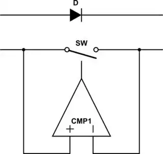
I would like to design a "safety" device able to tell me if a 3 parallel Li-ion cells module is voltage balanced or not.
EDIT (after @winny's comment): It’s needed if the user connects cells with different SOC/voltage, for e.g. if the cells are easily removable from the battery pack (in order to be easily replaced if needed).
Expected functionalities
N.B. Here I present the full functionality I would like to perform at the end in order to give you the global overview BUT this is not a DO IT FOR ME question. I just ask help for detecting the anomalies (not balanced cells and reversed cells) and then close a switch (starting from that, I will probably succeed in light some LEDs myself, hopefully...).
Considering 3 cells C1, C2 and C3 with corresponding voltages (potential difference at cell terminals): V1, V2 and V3:
- I want to detect if one of the 3 voltage differences (i.e. V12=V1-V2, V13=V1-V3 and V23=V2-V3) is higher than a threshold Vmin (e.g. Vmin=0.01V).
- If yes then light a red LED corresponding to the not balanced cells (at least 2 LEDs).
- If no, then close a 3 normally open switch contacts in order to connect all the cells in parallel and to allow current flow from the parallel module (global module current around 20 A max).
- Also it would be interesting to check if one cell voltage (e.g. V1) is negative in order to detect a possible cell reversion by the user. So, if the 3 cells are well balanced but V1 is negative, that means: all the cells are reversed and so don't close the switches and light the 3 LEDs. Else, if one cell is reversed, it should be detected at step 1.
My questions are:
- Is it possible to design this kind of device with few elementary and cheap components (e.g. op amp, resistor, diodes, transistors, etc.) ? Again, I don't ask you to tell me how to design the full functionality but for example if you can tell me how to close a switches after detecting the anomalies (not balanced cells and reversed cells), it will be perfect for me
- Do you know about a commercially available devices which do quite the same (or could be easily adapted or twisted)?
First naive pseudo-proposal
As neophyte, I thought use an op amp as differential amplifier in order to detect the voltage difference and then close a switch. I fund this kind of configuration which do closely what I want to achieve for one voltage comparison (see explanations at the end):
The problem for me is the need of a lot of components (ressitors, diodes, transistors, etc.) just for one voltage comparison. So I need 3 times this circuit for the whole detection... Any idea of a much more simpler solution?
Circuit explanations (from here)
Here the circuit above acts as a light-activated switch which turns the output relay either “ON” or “OFF” as the light level detected by the LDR resistor exceeds or falls below some pre-set value. A fixed voltage reference is applied to the non-inverting input terminal of the op-amp via the R1 – R2 voltage divider network. The voltage value at V1 sets the op-amps trip point with a feed back potentiometer, VR2 used to set the switching hysteresis. That is the difference between the light level for “ON” and the light level for “OFF”. The second leg of the differential amplifier consists of a standard light dependant resistor, also known as a LDR, photoresistive sensor that changes its resistive value (hence its name) with the amount of light on its cell as their resistive value is a function of illumination. The LDR can be any standard type of cadmium-sulphide (cdS) photoconductive cell such as the common NORP12 that has a resistive range of between about 500Ω in sunlight to about 20kΩ or more in the dark. The NORP12 photoconductive cell has a spectral response similar to that of the human eye making it ideal for use in lighting control type applications. The photocell resistance is proportional to the light level and falls with increasing light intensity so therefore the voltage level at V2 will also change above or below the switching point which can be determined by the position of VR1. Then by adjusting the light level trip or set position using potentiometer VR1 and the switching hysteresis using potentiometer, VR2 an precision light-sensitive switch can be made. Depending upon the application, the output from the op-amp can switch the load directly, or use a transistor switch to control a relay or the lamps themselves.
