I've got what I think is an answer to the question you meant to ask, based on your previous question. This circuit should provide a means of detecting a current induced in a coil with tunable sensitivity.
Theory of operation: op-amp as a comparator. R4/R5 provide a voltage reference at one terminal, R1/R2/R3 provide a voltage reference at the other. Current induced in the coil produces a voltage across R7. D1/D2 are clamp diodes to protect the amplifier; these may be omitted if your op-amp has its own input protection.
In this circuit, the values are somewhat arbitary, and the only thing that's important is that they are symmetrical and fairly large. (That's the advantage of this design as opposed to the current-based BJT amplifier, it requires a lot less engineering).
Observe that twiddling R1 across the centre of its range should turn the LED on and off. (Precise LED part number isn't important, any 20ma red or green LED should do.)
Put your multimeter in voltage mode across A and B and adjust R1 so that the LED is off, and the voltage between A and B is in the range you want to detect (<1v). The LED will then come on when an alternating current is induced in the coil.
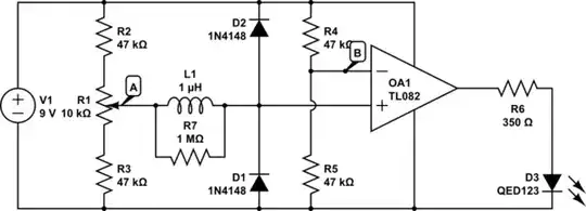
simulate this circuit – Schematic created using CircuitLab
