2

For the past year or so I have been 3D printing various windmill designs for my garden just as experiments and ornaments. Almost without exception, everybody who sees them asks me when I am going to start generating some electricity from them. I usually just smile and nod but then I started wondering if I could at least light up an LED or two to shut these people up.

So, I started an investigation into the feasibility: I generally have quite low windspeeds (<5 m/s) and my windmills are very small (200-400 cm2 blade sweep). Assuming around 10% efficiency I should still be able to extract 10-200 mW and much more on a windy day or from my better designs.

Looking at the datasheets for standard 5mm LEDs they seem to take up to 20 mA at 2.5-3.5 V (<70 mW) so it definitely looks doable.

Next step was to find a generator small enough for the job. Standard toy/model motors are a none-starter as they all need to turn at several thousand RPM to generate anything useful. Stepper motors are a better bet as they are designed for slower speeds but tend to be relatively quite large or the smaller ones are geared which would reduce my efficiency even more. I was on the verge of winding my own generator when I came across this on Amazon.

This seemed perfect so I bought a couple and sure enough they can light an LED even when turned by hand. They seem to be rated down to 3 V at 300 RPM which should be achievable by most of my windmill designs and also should be enough to power an LED.

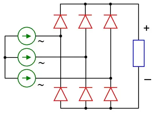
Now we come to the problem though: How do I convert the 3-phase output of the generator to light up an LED at the lowest possible wind power without burning it out on a windy day?

I first looked at simply connecting a current limiting resister in series with the LED and pushing one phase directly through it but even a 100 Ω resistor caused too much of a voltage drop and stopped the LED from lighting up.

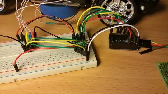
I then started looking at bridge rectifiers and current-limiting circuit diagrams, but being new to electronics this just made my head hurt so I thought I would ask for some expert help:

Can somebody show me a circuit which will take the output from my generator and power one or more LEDs safely with minimum loss of power whilst still being small enough to attach to a very small windmill?

ocrdu
  • 8,705
  • 21
  • 30
  • 42
  • (Answers may be slow because it looks tricky to keep it safe for the LED(s), easy to understand (assemble, purchase) while "lighting" at minimum RPM.) – greybeard Jan 18 '23 at 15:33
  • If generator is a low voltage, Use a 3 phases rectifier and then a dc-dc converter (low voltage, quasi 3-30V in, quasi 1-30 V out). Add a battery if needed ... – Antonio51 Jan 18 '23 at 15:44

2 Answers2

4

As with any LED, you need to limit the current through the LED; classically, that is done by keeping the supply voltage within a defined range, and adding a series resistance.

So, your LED wants DC, anyways. So, the first thing you'd do is attach a three-phase rectifier to actually make use of as much power as you get from the generator:

Three-phase full-wave rectifier
source: wikimedia commons, user zureks, CC-BY-SA 3.0

The green current sources represent the leads coming out of your generator (which hopefully are connected internally exactly like this). The blue rectangle here would be your load, e.g. an LED with a series resistor. The red rectifier diodes would ideally not have a lot of forward drop – so, something like Schottky diodes would work; they don't need a huge current rating, as your LED can't (and shouldn't) deal with more than a couple dozen milliamperes anyways.

schematic

simulate this circuit – Schematic created using CircuitLab

You could dimension that series resistor such that the current at the highest probably voltage (just try turning it as fast as you think it would turn on a windy day, measure with multimeter) would result in the maximum allowable current for the LED (e.g. 20 mA). That would make the circuit safe, but also dimmer than necessary – under less wind, you'd only get very little current and hence brightness, and under heavy wind, the resistor will be converting most of the power to heat, instead of the LED converting it to light. (Look for "LED series resistor here" – hundreds of answers explaining how to select a series resistor.)

So, first things first: add a 50V (or more) rated capacitor in parallel to the load (simply to even out the pulsating voltage, and to make things easier henceforth, by reducing the peak voltage). Your product page (sadly, no datasheet at all! shoddy documentation.) proclaims 24V. I'll take that as a maximum and run with it.

Cheapest method: get a linear voltage regulator, like the LM317, that allows you to build a constant-current source using an external adjustment resistor (again, "LM317 constant current" will help you find answers). At voltages sufficiently higher than the forward voltage, you will get a constant-brightness LED.

schematic

simulate this circuit


Added links to products that on superficial inspection would probably work for your use case


LDO option

schematic

simulate this circuit

Marcus Müller
  • 88,280
  • 5
  • 131
  • 237
  • 2
    (How about substituting one side of the rectifier by LEDs? (Obviating LED1)) – greybeard Jan 18 '23 at 15:58
  • @greybeard you can do that, but then it becomes hard to limit the current through the LED, which was the point to begin with. – Marcus Müller Jan 18 '23 at 15:59
  • `hard to limit the current through the LED[s]` I don't think so; the current through the LEDs still is the current through the voltage regulator/current limiter (but for being spiky - far from as bad as with a single phase rectifier with a capacitor)(I might skip the capacitor entirely). – greybeard Jan 18 '23 at 16:03
  • @greybeard If the reverse voltage is high enough and the peak voltage from the generator is low enough, why not. – winny Jan 18 '23 at 16:04
  • @greybeard exactly; you'd need to remove C1, to not have a low-impedance "bypass", but then it'd work. – Marcus Müller Jan 18 '23 at 16:28
  • Fantastic answer Marcus, this is exactly what I needed! Still a little worried about the voltage drop over all these components as I don't have much to play with. Will the LM317 take care of that? – Andy Ashwood Jan 18 '23 at 17:09
  • No – it just ensures that the maximum current is limited; if your supply voltage drops too low, you'd get lower current. Note that using all three phases in a full-wave rectifier (hence the six rectifier diodes) will allow you to, on average, extract significantly more power from the generator. – Marcus Müller Jan 18 '23 at 17:21
  • Think of the dashed box in my last schematic as "self-adjusting series resistor" which is programmed to always have the right value so that 20 mA flow – sadly, it needs a minimum drop of ca. 3V for itself. – Marcus Müller Jan 18 '23 at 17:22
  • by the way, there's also alternatives to LM317 + pass transistor for constant current sources, as built within that dashed box; things like [this](https://uk.farnell.com/diodes-inc/al5890-20p1-13/led-driver-constant-current-powerdi/dp/3755394); but I don't know how eager you are about integrating surface-mount components… – Marcus Müller Jan 18 '23 at 17:49
  • " sadly, it needs a minimum drop of ca. 3V for itself." This is going to be a problem as voltage is going to be about 3V to start with :( Can you get **really** small transformers so I can boost the voltage? – Andy Ashwood Jan 18 '23 at 18:17
  • You can even make them yourself! Again, the the past full-wave rectification gives you a free bonus on your voltage. But you might have already incorporated that in your math! But if that's the case, simply go a different route; say you've got a white LED with a 2.8V nominal forward voltage. Get a 2.5V output LDO whose input voltage can be as high as you believe the voltage can go. Directly connect the LED to that. – Marcus Müller Jan 18 '23 at 22:30
  • I got the three volts from the generator info as I clocked a couple of my windmills doing around 300rpm which is the slowest rotation quoted which I assume corresponds to the 3V quoted as the lowest voltage generated. I don't quite understand what this 'different route' is though. What is an LDO? – Andy Ashwood Jan 19 '23 at 10:28
  • ah, you forget that you get \$\sqrt 3\$ of the effective AC voltage as DC voltage after 3-phase rectification (that's why I'm advocating for it). LDO stands for "low-dropout", and is the term usually used for a specific architecture of voltage regulator which requires only a small difference between in- and output voltage. Sadly, that architecture is typically not able to be "abused" as constant-current source as the LM317 is. However, since they are quite precise in regulating the output voltage, that's not too bad: you can just use one to produce a voltage just below the maximum forward… – Marcus Müller Jan 20 '23 at 08:17
  • … voltage of the LED, and thus be sure that the LED never burns out. – Marcus Müller Jan 20 '23 at 08:27
  • Well spotted! That brings the input up to ~5.2V but I still don't like the idea of loosing 3V to the LM317. I'm not sure what the voltage drop would be over the rectifier diodes but I am probably only looking at around 1.5V to the LED :( I suppose that should be fine for a red LED but I was hoping to use some nice bright white ones. I think I need to build bigger windmills! – Andy Ashwood Jan 20 '23 at 11:44
  • Just as an afterthought, could you post an LDO version of the circuit I can try for comparison sometime? – Andy Ashwood Jan 20 '23 at 11:47
  • Yep, Done that :)! – Marcus Müller Jan 20 '23 at 18:26
4

schematic

simulate this circuit – Schematic created using CircuitLab

Something like this will provide a voltage doubling function, and the capacitor will perform some current limiting with little wasted power. Performance will depend on the source impedance of V1, and there will be considerable current in the capacitor that will present a drag on the fan. But that might also function as a mechanical voltage*current (power) regulator.

Voltage doubler LED driver

I wasn't able to show LED current, so I used voltage on the 100 ohm resistor. Thus the 4.8V peaks will be 48 mA.

Here I added a second phase. You can try a third phase which should give rather more clean DC.

Two of three phases

Added a current limiter for about 20 mA, where V1 = 15V, and V2 is 3V. Change R1 for other current setting, where I = 0.7 / R1.

Voltagesd for current limit 20 mA Current limit 20 mA

PStechPaul
  • 7,195
  • 1
  • 7
  • 23
  • Now, what about both other phases? (100 Hz is a bit high, guessing 2p=3 from the Amazon picture of the stator.) – greybeard Jan 21 '23 at 01:37
  • I'd use the same circuit on all three phases and light three LEDs. Or you might be able to add steering diodes from C1/D1 junction to a single LED. – PStechPaul Jan 21 '23 at 01:48
  • (I "simulated it": works like a charm paralleling them with another three Shottky diodes. (Was pretty sure so voted before.)("Measure" the current by typing the expression or clicking on the terminal you want to know about(and deleting the expressions you're not interested in.)(Much better than the component graves I thought up - VIENNA, anyone?)) – greybeard Jan 21 '23 at 01:59
  • Wow! You guys are great. Thank you so much for all your work on this for me. – Andy Ashwood Jan 21 '23 at 10:20
  • I like the idea of having three circuits and three LEDs. Just to be clear: V1 and V2 in the diagram are two of the phases from the generator and each circuit gets a different pair of phases. so: P1/P2, P2/P3 and P3/P1? – Andy Ashwood Jan 21 '23 at 10:24
  • I tried simulating this circuit with higher voltages (windy days) and it looks like it would probably blow the LEDs. Can somebody confirm this? – Andy Ashwood Jan 21 '23 at 11:57
  • See revised schematic with current limiter. – PStechPaul Jan 21 '23 at 15:31