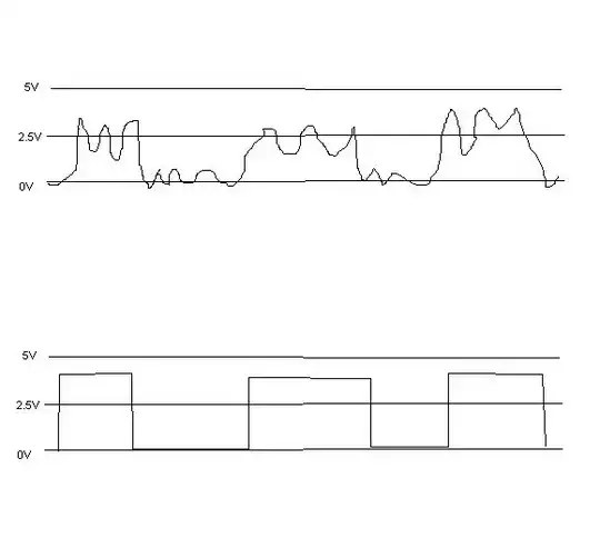
I am working on a simple VLC link.
 A square wave input with 1 MHz signal is coupled with the direct current (DC) by a bias tee (mini circuits ZFBT-4R2GW-FT+) to drive the lighting of the white LED. Next, two plano-convex lenses are placed in front of the LED. These guide the emitted light onto the PIN photodetector. After that, the received signal is processed offline in MATLAB software.
There are few questions based on this setup:
- Why did the oscilloscope (bandwidth 1 GHZ and sample rate of 5GS/sec) fail to display any pulse signal?
- Does the position of my lenses affect the received optical power?
- Is the bias tee really needed for faster modulation? No pulse signal appeared on the oscilloscope even without the bias tee for square signal with 500 Hz frequency.