7

I can solder and use basic features of multimeter so excuse my ignorance.

This is driving me crazy, this a potentiometer from speakers which lost left channel sound. I disconnected the volume control (potentiometer) connected directly and both channels worked. So the potentiometer was the culprit. I unsoldered the black (ground) wire to make sure it wasn't cables fault.

It shorts between pin1 to pin2 and pin3 and all the points ground (black), but they never touch. How is this possible? Actually red wire goes to pin1 and then dead end.

Black = ground,
Red = right channel,
White = left channel

I set the multimeter to beep mode to check it.

enter image description here

JRE
  • 67,678
  • 8
  • 104
  • 179
BeBu
  • 71
  • 4
  • 2
    Are you taking the measurement in resistance mode, or continuity mode (beep mode)? In other words, is it a dead short, or just a low resistance path. Also, are you taking the measurement with the potentiometer housing on or off? – Yet Another Michael Jan 15 '23 at 19:14
  • 4
    The beep/continuity check on a multimeter DOES NOT indicate a short circuit - the meter will beep if the resistance between the probes is some low value - about 40 Ohms for one of my meters. If you want to check for an actual Zero Ohm short circuit, you need to make a resistance measurement. – Peter Bennett Jan 15 '23 at 19:15
  • 1
    _"It shorts between pin1 to pin2 and pin3 and all the points ground (black), but they never touch. How is this possible?"_ - pins 2 and 3 are connected together on the PCB. There might also be an unintentional solder bridge between pins 1 and 2. Try scraping between the pins with a knife to clear any possible bridges. If that doesn't clear the short then unsolder the pot track pins and test it out of circuit. – Bruce Abbott Jan 15 '23 at 22:45
  • 1
    @BruceAbbott - Agree on the solder bridge. Unclear if the left and right red wires are connected, but I think the bottom picture you can clearly see someone was digging between pins 1 and 2, and as you mention pins 2 and 3 are connected in the bottom picture via the PCB. Also noteworthy is the possible solder bridge between black and red wires in the left side of the bottom picture, with black going to pins 2 and 3. If red on the left and red on the right are connected out of the frame then that could be the connection. In general, the soldering here is a big mess. – Chuck Jan 16 '23 at 17:01

3 Answers3

6

You don't show the pot wiper contacts so it's hard to tell if those are the problem or not.

There's not much that could short out on the parts shown, could be some solder or whiskers between the solder pads, or the pins on the pot.

It could also be some carbon between the pot resistive tracks although I don't see anything obvious in the photo.

Whiskers are very thin filaments of metal that grow out of the solder, they didn't used to be much of a problem because the lead in the solder helped keep them from forming, with lead free solder they're more common.

First check to see what the actual resistance is between the pins. With the wiper contacts off like shown you should have an open circuit between pin 1 and ground.

If you show a low resistance try using a small brush to clean between the solder pads and pins, you could also resolder the pot pins if your soldering technique is good. Also you might try checking it with the cables removed completely.

GodJihyo
  • 17,628
  • 1
  • 16
  • 45
  • hey, thanks for the answer, I'm taking measurements with disassembled pot, as shown on the pic. To make this question simpler: Multimeter in beep mode Whenever I touch pin1(right channel) and ground anywhere it beeps, so it means there's a connection, it's called closed circuit if I'm not mistaken, should be open circuit as you said. – BeBu Jan 15 '23 at 23:18
  • 2
    @BeBu "Beep mode" (continuity testing) is not useful here. A resistor is neither a continuous connection nor an open connection. You want to measure resistance. – Sneftel Jan 16 '23 at 09:43
  • Well, I'm not interested in resistance, I'm trying to find where and why Red(right channel) and Black(ground) short/touch each other, which they shouldn't. – BeBu Jan 16 '23 at 13:28
  • 3
    @BeBu Several of us have suggested checking the actual resistance, there's a reason for that. The amount of resistance you read can help us determine what the problem is. The continuity function (beeper) will not tell you the difference between a dead short and a low resistance, each of which may indicate a different problem. – GodJihyo Jan 16 '23 at 14:27
5

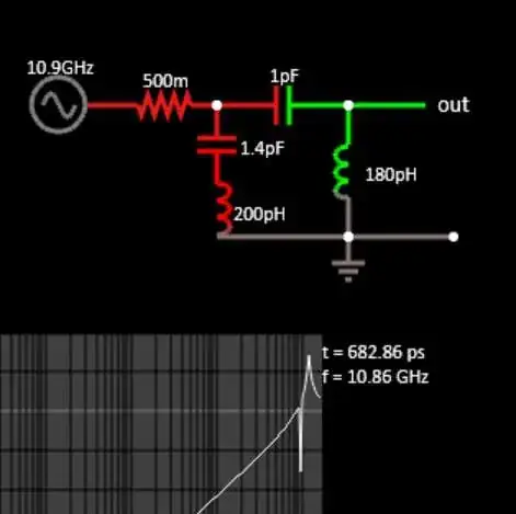
I believe schematic of this board is like this (in on the right, out on the left, sorry):

schematic

simulate this circuit – Schematic created using CircuitLab

The wipers would be 'U' shapes oriented in opposite directions.

To test this with the pot assembled, measure the resistance from 6 and from 5 to 2 & 3 (they are shorted together). Pot position should not matter.

Then, if both show continuity and reasonable resistances, measure the resistance from 1 to 2&3 and from 4 to 2&3, both should vary smoothly with pot shaft angle from near 0Ω to close to the values measured in the above test.

Here is how I think the wipers are disposed (green):

enter image description here

If the pot shows open connections, it's possible the joints between the conductive ink and the pins have broken (inside my red circle). If (and only if) the testing indicates an open maybe you can try gently resoldering them. First check that the wipers are not bent, fallen out of position or otherwise not contacting the two places they each have to bridge.

The other ring (with the end hanging free) is a silver conductive trace with black resistive material printed over the entire length where the wiper contacts.

The next two rings moving inward are the potentiometer elements (the conductive ink ends just under the black resistive ink) at each end.

The innermost small ring again is conductive ink with resistive over it.

The resistive material is printed over the conductive to give a good (and quiet) connection to the wiper without greatly increasing the contact resistance.

Spehro Pefhany
  • 376,485
  • 21
  • 320
  • 842
4

It's a standard dual potentiometer.

enter image description here

The two wipers are shown in orange.

Here's the schematic.

enter image description here

The points marked 'pin 2' and 'pin 3' are connected to the PCB ground plane. Hence the short.

It's not clear how the point marked 'pin 1' can short to ground.

vu2nan
  • 15,929
  • 1
  • 14
  • 42