4

This control board is from a mini-split heat pump. It sits on the outside of the unit and receives signals from a remote control. It's from this discussion here.

enter image description here enter image description here

It's a single-sided board - am I getting the schematic correct, and is this typical for an infrared sensor e.g. used with remotes?

The brown and orange aren't clearly identified. If those were accidentally swapped will they just light the wrong light? Or could something worse happen?

schematic

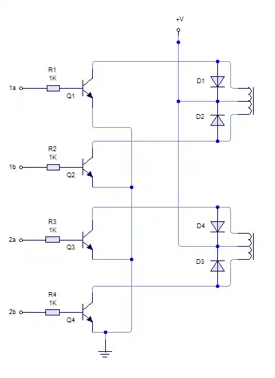
simulate this circuit – Schematic created using CircuitLab

Bonus questions: Why two capacitors? What's the point of the resistor (is that a resistor?) in series with red/supply?

  • Bend the three-terminal device away from the board to get the part number on its flat face. LAMP1 and 2 should probably use the LED symbol. – Transistor Jan 14 '23 at 07:46

2 Answers2

7

The two caps provide good supply bypass. The electrolytic does the low frequencies and the ceramic handles the high frequencies.

R1 is an idiot resistor. Imagine if U1 fails short circuit -- R1 keeps currents safe.

Autistic
  • 14,235
  • 2
  • 27
  • 65
4

Chances are the three-terminal component is an IR receiver.
Either there is a hole/window in the casing, or that would need to be somewhat transparent to IR.

greybeard
  • 1,469
  • 1
  • 4
  • 17