4

I have a 1970s-vintage video generating board that I'd like to do some work with. I do not have the PSU that it was meant to be connected to. The board wants +/-5V, -12V DC, plus a small 6V AC "reference" rail that shares the same common/ground rail.

I'm a bit puzzled as to the simplest way to recreate this. The original PSU's schematic looks like this:

enter image description here

The 6VAC connection is marked "R" at left, and as you can see, it is connected to one of the transformer tap outputs, bypassing all the rectifier stuff, and its current returns back to the system via the common ground rails to the center taps.

The DC supplies are easy-- this switching quad output Mean Well on amazon puts out +/-5 and +/-12. But this leaves me without an answer for the 6VAC line. I can separately find a 6V transformer but that results in an independently isolated AC. (And that's not helpful to me... right?)

There are modern linear supplies like this one that I assume could be rigged up to pull out an AC line but they don't seem to ever support a -5VDC line.

This isn't for super robust long term use so I'm willing to rig something up to get it going, but I'd like some guidance or suggestions. Short of finding the old transformer and literally rebuilding the original 70s PSU design, is there some way to create a viable power supply that meets this need with modern bits and pieces?


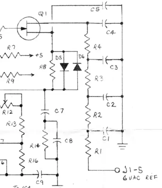
Further information as requested by kind commenters: The schematic for the video board showing use of the 6VAC line is linked here. 6VAC connection is on the right of the diagram, entering an RC ladder and going into the drain of an old JFET: enter image description here (Part values are not marked on this diagram, they are in a different document (page 5), which is annoying.)
BZo
  • 1,575
  • 1
  • 11
  • 22
  • 3
    I suggest you look at what the 6V reference is needed for, and maybe trace the circuit to see what voltage/current is actually required. It may be that a simple oscillator can supply a signal that does the job. It could be reference for an RTC or frame synchronisation. Without that info the only guaranteed option is a 6V transformer. – Finbarr Jan 09 '23 at 17:22
  • Thanks. I am out of my depth on the electrical engineering analysis for that (ie, I have a schematic of that circuit but I can't determine the answers to your questions there). The reference line runs into a sort of RC ladder and then into the drain of a TIS58 FET. I don't want to overly complicate this question with all the info about the video board use, although if there's no simpler solution to the 6V I can ask another question and link it for the analysis. – BZo Jan 09 '23 at 17:41
  • If you can add the image of where that reference goes, the talented folks here can deduce it's operation quickly. – rdtsc Jan 09 '23 at 17:56
  • 1
    `I can separately find a 6V transformer but that results in an independently isolated AC.` ... only if you do not connect one side of the secondary winding to DC GND – jsotola Jan 09 '23 at 18:01
  • @rdtsc I thank you for the prompt, and reasonable enough. I've added a clip of that schematic and a link to the full thing above. – BZo Jan 09 '23 at 18:07
  • @jsotola Can I do that though? That's out of my engineering depth. If I hook over the other side of a separate transformer into the DC ground of a separate DC power supply isn't that... making a hash of it? I really don't know-- if I'm wrong please do let me know as that would be easy to do, but I won't without knowing it won't blow things up! :):) – BZo Jan 09 '23 at 18:09
  • 1
    Looks to me like the reference is used just to get a 60Hz signal that's then multiplied up using a PLL to generate a timing clock without using a crystal or calibrated oscillator. You'll probably find the unit runs without the reference altogether, though it may be less stable. – Finbarr Jan 10 '23 at 11:14
  • @Finbarr: I wouldn't be surprised if the unit fails without a reference, but I think simply simply taking the output of a simple 60Hz square wave generator and using that, possibly with a series cap and a resistor to ground (I'm not sure which way the FET switches) would likely suffice. No need for anything particularly fancy. – supercat Jan 10 '23 at 16:53

2 Answers2

11

I can separately find a 6V transformer but that results in an independently isolated AC. (And that's not helpful to me... right?)

Nope.

The simplest way to go is what you said, a separate transformer. Connect one lead from the secondary to system GND, and the other lead will be your 6 Vac waveform with the system GND as its reference - exactly as in the original design. There is nothing in the original design that is phase-dependent, so you can ground either secondary lead.

UPDATE:

As for transformer size, it can be very small. Based on the added schematic, the current load is very small. You don't say the values of R1 - R4, but in that circuit there is no reason for any significant current.

AnalogKid
  • 16,865
  • 1
  • 13
  • 25
  • Huh. OK, just to make sure I'm super clear here. Use a (a) commodity switching DC power supply that provides the needed DC rails plus a separate (b) 120VAC<->6VAC (say) transformer. I use one tap of that transformer's secondaries as the reference line needed, and I connect the other secondary tap of the transformer to the DC power supply's GND terminal (along with all the other returning GND lines from the board I'm powering). And there's no issue there? Thanks! – BZo Jan 09 '23 at 18:26
  • 2
    Correct, no issues. The switching supply has a fully isolated transformer in there somewhere, and the 6 V secondary is fully isolated. You can connect one wire from the 6 V transformer to any of the switchers output terminals, and that terminal's voltage is now the reference DC level that the 6 V AC is added to. In your case, connect it to GND. – AnalogKid Jan 09 '23 at 20:53
  • Oh fascinating. Gotcha! I had some sense that doing that would sort of "cross the streams" in incompatible ways. But your description makes sense. Thanks for the assist. – BZo Jan 09 '23 at 21:08
  • Quick followup question: how do I size the 6V transformer correctly? Should it be as big in VA spec as the original PSU's transformer that supplied all the rails? Or can it be smaller since it will only handle the reference input? (Or if there's math to figure out an in between, getting something large is presumably safer) Thanks! – BZo Jan 09 '23 at 23:43
  • 1
    See the answer update. – AnalogKid Jan 10 '23 at 05:08
  • 1
    Be caution with small transformers - thay are very "soft" i.e. 6V will be at full specified load. Without load voltage will be much highier. – ufok Jan 10 '23 at 06:36
  • Thanks. Sounds like the way to think about it is that the additional transformer will only be “responsible” for the current drawn by the reference circuitry, and will be out of the path of current for all the other rails that share the same return path. – BZo Jan 10 '23 at 07:45
3

Assuming you can source one (given the current silicon chip market) you could use a 50Hz (or 60Hz) timing reference (e.g. ELM446) and a push pull driver into a centre tapped 1:1 audio transformer.

Connect the CT to GND and the ends to the push pull. AC couple the supply to prevent accidental DC current.

It won't generate a sine wave but by the looks of the 2nd schematic that should not matter much as it's heavily filtered anyway.

I would suggest testing this idea using a signal generator first.

Jay M
  • 3,753
  • 15
  • 30
  • 2
    that will not work, if that 6VAC are used for some kind of mains synchronization. – tobalt Jan 10 '23 at 06:31
  • @tobalt Yes,obviously that is true, but my guess from looking at the schematic and the product (which looks like a sort of old school monochrome ultra low resolution GPU) that this signal is used to generate the frame sync. – Jay M Jan 10 '23 at 11:59