It's important to understand the difference between linear circuit theory and physics. Many beginners attempt to use a SPICE-like circuit simulator to find truths about physics, without realizing what they're looking for is not there.
Linear Circuit Theory
In linear circuit analysis, we assume that Kirchhoff's Voltage and Current Laws must always be true - voltage and current must exist in a closed loop. A circuit simulator generates the loop equations in matrix form and applies linear algebra to solve it. It makes no attempt to analyze the electric field, magnetic field, trapped charges on a piece of metal, etc.
Thus, what you attempted to simulate - an open-ended capacitor with nothing connected to it - is technically an illegal move. It's like division by zero, as far as linear circuit theory is concerned, this "circuit" is meaningless and cannot be analyzed. It's called a floating node - a point in a circuit where nothing is connected to it. By the rules, the voltage here is undefined.
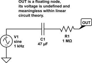
simulate this circuit – Schematic created using CircuitLab
But why does the circuit simulator still shows an output? When the circuit simulator sees you're trying to simulate circuits with a floating node, it simply insert a huge virtual resistor to ground to force the formation of a closed loop, allowing the use of KVL and KCL again. Typically, the resistor is on the order of gigaohm to teraohm.
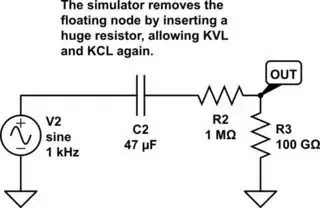
simulate this circuit
Why would you want to do this? In the real world, any voltmeter or oscilloscope has a large-but-finite input resistance. If you construct this open-ended capacitor circuit in the real world, the moment you put a voltage probe onto it, the loop is completed anyway. The circuit with a probe and the circuit without, are different physical systems. In most applications, only the first form has a practical purpose in engineering. The default behavior of inserting virtual resistance by a circuit simulator is essentially doing same thing.
In conclusion, what you're seeing here is just the voltage experienced by an extremely huge resistor, connected with a capacitor in series across a voltage source. There's nothing mysterious about it. You can even remove your 1 MΩ resistor R2, since the same result happens without any series resistor. The following circuit produces the same result in a simulator.
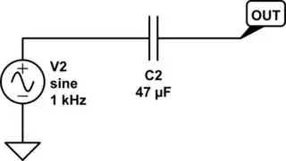
simulate this circuit
Physics
In one comment, the OP clarified that:
My question comes more from a physics standpoint
So the real question here is: what is physically happening on the metal plate at the open-ended side of the capacitor? What is its actual electric potential of that plate according to the laws of physics of Faraday and Maxwell? If its electric potential really is what the circuit simulator shows (even though the simulator does not simulate any electric field), why does it "act like a wire"?
In fact, this question has already been asked before. In What is physically happening when there is a square wave input on the left plate of a capacitor and open circuit on right plate of a capacitor?, its OP asked:
Why is it that the voltage transfers [across the capacitor], but it doesn't in [an open circuit] where Vout is 0 V. Is it related to the capacitors ability to store charge? If so, why does this matter as in the first picture the capacitor is not holding any charge as it's never charged due to a lack of current. And the lack of current is due to lack of a path for the current to flow to ground.
I'd like to inform you that these questions is one level deeper than circuit analysis, and most engineers are not equipped to answer your question.
Electronics operates at a model level that sits above where your question is at.
Your question is like asking why it is that 4 times 5 is 20. Most answers will form around the idea that adding up 4, 5 times, makes 20 or that adding up 5, 4 times, makes 20. None of the answers will dig deeper until you ask that question to a specialist of such questions, namely an abstract mathematician.
Electronics, at the level most try to gain it, assumes certain ideas into place. While they are true enough at the level needed, these devolve into circular arguments when you ask why they are what they are. Your question needs to be handled by a specialist of such questions, namely an experimental physicist. So this really isn't the right place unless you are lucky enough to find one here. I'm not one.
He then attempted to explain it with a detailed answer from a physics-first perspective. See if it answers your problem. If not, I'd suggest you to try Physics Stack Exchange instead.