I understand that a capacitor can pass high frequencies and block low frequencies, because of its impedance properties. Now, why do you need to put in series a resistor? Doesn't it already filter frequencies on its own?
The key is to understand the difference between an ideal voltage source in circuit theory and a real power supply in the real world.
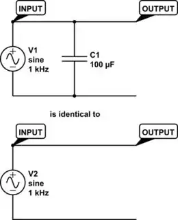
Ideal Circuit
An ideal voltage source always keeps its output voltage the same by magic. No matter what is being connected across the ideal voltage source - resistors, capacitors, inductors, they have absolutely no effect on its output voltage. It cannot be "loaded down", even if it means the voltage source has to deliver millions of amperes to achieve this result. It's also why an ideal voltage source in circuit analysis cannot be short-circuited, or be connected to a different voltage source - it's essentially division by zero, an illegal move.
In ideal circuit theory, connecting a capacitor across an AC voltage source does absolutely nothing to its voltage, regardless of whether this voltage is signal or noise - an ideal source is an ideal source.
simulate this circuit – Schematic created using CircuitLab
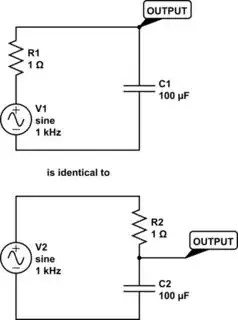
Practical Circuit
A real circuit, like a battery or a power supply, always has a non-zero output resistance or reactance - it's the "hidden" R in RC. It's why, in a practical circuit, a capacitor can be connected directly across the power supply and works as a filter on its own. Because the existence of a resistor after the ideal voltage source, now its voltage changes depending on the load. The capacitor "loads down" the voltage from the power supply, thus creating a filter.
simulate this circuit
In other words, the large capacitor on the circuit board is only half of the filter, another hidden half is the internal resistance of the power supply itself. When they're combined, a voltage divider is created. In fact, a filter's performance can change dramatically under different source and load impedances.
Forgetting this fact can lead to practical problems - for example, many engineers learned it the hard way that a powerline EMI filter's noise attenuation won't be as good as its datasheet suggests, since it's measured with 50 Ω source and load in standard RF test instruments - a condition you will almost never find in a power supply!
So the bottom-line is, at the very least, R is here to enforce physical reality and to stop the math from breaking down.
To be even more realistic, the power supply is modeled as a voltage source followed by output resistance and wiring inductance. The capacitor is modeled as a ideal capacitor, with parasitic inductance and series resistance.
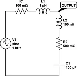
simulate this circuit
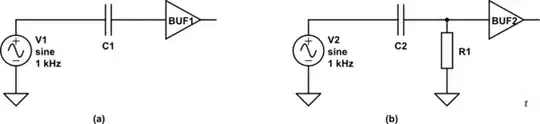
It is important to understand that decoupling is not the process of placing a capacitor adjacent to an IC to supply the transient switching current [...] rather it is the process of placing an L–C network adjacent to an IC to supply the transient switching current [...] All decoupling capacitors have inductance in series with them. Therefore, the decoupling network is a series resonant circuit.
- Henry W. Ott - Electromagnetic Compatibility Engineering