I have a three phase inverter model and I am investigating the effects of an increased switching frequency for pre-defined LC filter parameters. It is a simple MATLAB Simulink model: DC source, inverter, LC filter and constant value resistive load.
The voltage THD decreases when I compare figures for 4 kHz vs 6 kHz switching frequency, and I would expect that, but the current THD increases. Why is that happening?
fsw = 4 kHz


Sinusoidal PWM, modulation index = 0.95:

fsw = 6 kHz


Sinusoidal PWM, modulation index = 0.95:

Interestingly, for an 8 kHz switching frequency and all other model parameters stayed the same, the current THD is reduced:
fsw = 8 kHz


Sinusoidal PWM, modulation index = 0.95

CircuitLab abstract model is below.
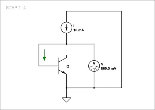
simulate this circuit – Schematic created using CircuitLab
Update:
I am also using common-mode capacitance 300 nF and 15 Ohm resistance between the load neutral point and ground.

When I plot the impedance graph, I can see a peak at ~5.6 kHz. Changing the common-mode capacitance affects the impedance peak, and subsequently, line current THD. For both Ccm × 10 (3000 nF) and Ccm ÷ 10 (30 nF), the current TDH for a 4 kHz switching frequency is lower.
