6

I was looking at the following circuit. AFAIK, this is a low-pass Sallen–Key filter, with a VCVS instead of the op-amp.

I started to work out the transfer function, but somehow I got lost at a certain step.

Enter image description here

First, you can use the common node to state:

$$V_{A}(s)=V_{1}(s)$$ and $$V_{D}(s)=\mu V_{C}(s)=V_{2}(s)$$ then the KCL for nodes at \$V_b\$ and \$V_C(s)\$:

$$\frac{V_{B}(s)-V_{1}(s)}{R_{1}}+\frac{V_{B}(s)-V_{C}(s)}{R_{2}}+\frac{V_{B}(s)-\mu V_{C}(s)}{\frac{1}{C_{1}s}}=0$$ $$\frac{V_{C}(s)-V_{B}(s)}{R_{2}}+\frac{V_{C}(s)}{\frac{1}{C_{2}s}}=0$$

multiplicating by \$R_{1}R_{2}\$ $$\frac{R_{1}R_{2}(V_{B}(s)-V_{1}(s))}{R_{1}}+\frac{R_{1}R_{2}(V_{B}(s)-V_{C}(s))}{R_{2}}+\frac{R_{1}R_{2}(V_{B}(s)-\mu V_{C}(s))}{\frac{1}{C_{1}s}}=0$$

$$\frac{R_{1}R_{2}(V_{C}(s)-V_{B}(s))}{R_{2}}+\frac{R_{1}R_{2}(V_{C}(s))}{\frac{1}{C_{2}s}}=0$$

$$R_{2}(V_{B}(s)-V_{1}(s))+R_{1}(V_{B}(s)-V_{C}(s))+\frac{R_{1}R_{2}(V_{B}(s)-\mu V_{C}(s))}{\frac{1}{C_{1}s}}=0$$

$$R_{1}(V_{C}(s)-V_{B}(s))+\frac{R_{1}R_{2}(V_{C}(s))}{\frac{1}{C_{2}s}}=0$$

$$R_{2}V_{B}(s)-R_{2}V_{1}(s)+R_{1}V_{B}(s)-R_{1}V_{C}(s)+\frac{R_{1}R_{2}V_{B}(s)}{\frac{1}{C_{1}s}}-\frac{R_{1}R_{2}\mu V_{C}(s)}{\frac{1}{C_{1}s}}=0$$

$$R_{1}V_{C}(s)-R_{1}V_{B}(s)+\frac{R_{1}R_{2}V_{C}(s)}{\frac{1}{C_{2}s}}=0$$

$$R_{2}V_{B}(s)-R_{2}V_{1}(s)+R_{1}V_{B}(s)-R_{1}V_{C}(s)+C_{1}sR_{1}R_{2}V_{B}(s)-C_{1}sR_{1}R_{2}\mu V_{C}(s)=0$$

$$R_{1}V_{C}(s)-R_{1}V_{B}(s)+C_{2}sR_{1}R_{2}V_{C}(s)=0$$

$$(R_{1}+R_{2}+R_{1}R_{2}C_{1}s)V_{B}(s)-(R_{1}+\mu R_{1}R_{2}C_{1}s)V_{C}(s)=R_{2}V_{1}(s)$$

$$(R_{1}+R_{1}R_{2}C_{2}s)V_{C}(s)=R_{1}V_{B}(s)$$

$$(R_{1}+R_{2}+R_{1}R_{2}C_{1}s)V_{B}(s)-(R_{1}+\mu R_{1}R_{2}C_{1}s)V_{C}(s)=R_{2}V_{1}(s)$$

$$R_{1}(1+R_{2}C_{2}s)V_{C}(s)=R_{1}V_{B}(s)$$ $$\frac{R_{1}(1+R_{2}C_{2}s)V_{C}(s)}{R_{1}}=\frac{R_{1}V_{B}(s)}{R_{1}}$$

$$(1+R_{2}C_{2}s)V_{C}(s)=V_{B}(s)$$

From the schematic you can tell

$$V_{2}(s)=\mu V_{C}(s)$$

$$(R_{1}+R_{2}+R_{1}R_{2}C_{1}s)(1+R_{2}C_{2}s)V_{C}(s)-(R_{1}+\mu R_{1}R_{2}C_{1}s)V_{C}(s)=R_{2}V_{1}(s)$$

$$(R_{1}+R_{2}+R_{1}R_{2}C_{1}s)(1+R_{2}C_{2}s)V_{C}(s)-(R_{1}V_{C}(s))-R_{1}R_{2}C_{1}s\mu V_{C}(s)=R_{2}V_{1}(s)$$

$$(R_{1}+R_{2}+R_{1}R_{2}C_{1}s)(1+R_{2}C_{2}s)=R_{1}+R_{1}R_{2}C_{2}s+R_{2}+R_{2}^{2}C_{2}s+R_{1}R_{2}C_{1}s+R_{1}R_{2}^{2}C_{1}C_{2}s^{2}$$

$$(R_{1}+R_{1}R_{2}C_{2}s+R_{2}+R_{2}^{2}C_{2}s+R_{1}R_{2}C_{1}s+R_{1}R_{2}^{2}C_{1}C_{2}s^{2}-R_{1}-R_{1}R_{2}C_{1}s\mu)V_{C}(s)=R_{2}V_{1}(s)$$

$$(R_{1}R_{2}C_{2}s+R_{2}+R_{2}^{2}C_{2}s+R_{1}R_{2}C_{1}s+R_{1}R_{2}^{2}C_{1}C_{2}s^{2}-R_{1}R_{2}C_{1}s\mu)V_{C}(s)=R_{2}V_{1}(s)$$

But here, I understand the way to go is using the fact of \$V_{2}(s)=\mu V_{C}(s)\$, but I got lost, how to group it to get the \$H(s)\$?

Peter Mortensen
  • 1,676
  • 3
  • 17
  • 23
avelardo
  • 495
  • 3
  • 10
  • 3
    Why do you want to solve it with a VCVS? are you trying to investigate the effect of a finite loop gain or something? I'd say is a lot easier if you assume an ideal op-amp to start – Designalog Jan 04 '23 at 07:20
  • 3
    Plus, I think you're forgetting the negative feedback around the VCVS to form a voltage buffer (assuming you don't want gain) – Designalog Jan 04 '23 at 07:21
  • 3
    Do you know how to solve it when the VCVS gain is unity? (i.e. walk before you can run?) – Andy aka Jan 04 '23 at 12:34
  • 4
    I think your simplified circuit is incorrectly drawn as the amplified voltage is not the voltage across \$C_2\$ but the voltage between \$C_2\$ and the output. – Verbal Kint Jan 04 '23 at 13:02
  • 1
    @ErnestoG, because I think it should be the same result of making the analytics with the ideal model of the opamp, and I'm (could be wrong) discarding the negative feedback since at this point it is not relevant (but later it is). – avelardo Jan 04 '23 at 17:36
  • @VerbalKint, you are right, it seems I overpassed that fact, but the basic relations aren't modified (I think). – avelardo Jan 04 '23 at 17:40
  • @Andyaka, no (I was thinking I knew it). – avelardo Jan 04 '23 at 17:40
  • I have a dilemma, because there are responses that directly answer the question and others that enrich the theme. – avelardo Jan 04 '23 at 21:10

4 Answers4

5

The fast analytical circuits techniques or FACTs described in my book on the subject offer a quick and convenient way to obtain the transfer function of this filter. However, it is important to note that the provided simplified schematic is wrong as the op-amp error voltage is wrongly taken across \$C_2\$. The correct equivalent circuit is shown below:

enter image description here

From there, you can apply the FACTs and start by analyzing the circuit for \$s=0\$ in which all caps are open. You obtain \$H_0\$ which is not the op-amp open-loop gain.

Then, you turn the excitation off - the input source is replaced by a short circuit - and you determine the resistance \$R\$ "seen" from the capacitors connecting terminals. The below picture shows the steps, some KVL and KCL are needed but this is pretty simple. And if you make a mistake, just solve the guilty sketch and straighten the all equation up without restarting from scratch:

enter image description here

There is no zero in this circuit because turning \$C_1\$ and \$C_2\$ in their high-frequency state (a short circuit) gives a 0-V output. Now assemble the time constants you have found and compare the response in phase and magnitude with a SIMetrix simulation:

enter image description here

The final transfer function appears in a clear and ordered manner - this is a low-entropy expression and it can be reworked to highlight salient characteristics such as the quality coefficient and the resonant frequency.

Verbal Kint
  • 20,420
  • 1
  • 16
  • 50
  • 3
    What do you mean by *"straighten the all equation up"* (seems somewhat incomprehensible)? – Peter Mortensen Jan 04 '23 at 17:29
  • 1
    @Verbal Kint: It's pretty interesting, I see many differences from the usual method. I'm verifying the source of the schematic to check the output voltages, It's something strange. Hey I have seen part of your book as someone on the school suggested to the group. Nice to meet you. Thanks. – avelardo Jan 04 '23 at 17:54
  • 2
    @PeterMortensen, it's probably lost in the translation : ) I meant if the final expression is wrong because one of the intermediate sketches for determining the time constants is bad, then fixing the guilty sketch *alone* will correct the entire expression without restarting from scratch. In French, it would be "remettre d'aplomb" but perhaps it does not make sense when used for an equation : ) Cheers! – Verbal Kint Jan 04 '23 at 19:25
  • 2
    @avelardo, glad if you liked the approach. The FACTs are a very interesting skill to acquire and I encourage you to further explore the method. Good luck with your studies! – Verbal Kint Jan 04 '23 at 19:27
4

Here comes my recommendation for finding the transfer function of a Sallen-Key filter:

  • Use only conductances y1....y4 for the passive components;

  • Write down the two node equations for the two node voltages Vb and Vc (with finite and fixed closed-loop gain A for the amplifier);

  • Solve for V2(s)/V1(s) and introduce y=1/R and y=sC.

Comment: When using conductances Y, the capacitors are considered from the beginning as sC - and, consequently, the transfer function has the classical standard form of a polynominal in "s".

LvW
  • 24,857
  • 2
  • 23
  • 52
4

The Sallen–Key circuit

schematic

simulate this circuit – Schematic created using CircuitLab

\$V_c = V_o \cdot \frac{R_4}{R_f+R_4} = \frac{V_o}{K} \: \: \: \text{where} \: \: \: K = 1+ \frac{R_f}{R_4}\$

The node equations for A and B are

$$\begin{align*} \frac{V_a-V_\text{in}}{R_1} + \frac{V_a-V_b}{R_2} + (V_a-V_o)sC_1 = 0 \\ \\ \frac{V_b-V_a}{R_2} + V_bsC_2 = 0 \end{align*}$$

Because there is negative feedback \$V_b = V_c\$ (virtual short). Substituting this for \$V_b\$ and solving the two equations with respect to \$V_a\$ and \$V_o\$ you get

$$V_o = V_\text{in} \cdot \frac{K}{s^2 + s(\frac{1}{R_2C_2} + \frac{1-K}{R_2C_1} + \frac{1}{R_1C_2}) + \frac{1}{R_1R_2C_1C_2}} $$

P.S.: There isn't any extra reward for finding the transfer function of circuits by hand.

Peter Mortensen
  • 1,676
  • 3
  • 17
  • 23
Carl
  • 3,646
  • 1
  • 14
  • 33
3

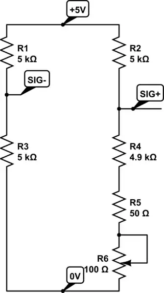
Well, we are trying to analyze the following circuit:

schematic

simulate this circuit – Schematic created using CircuitLab

When we use and apply KCL, we can write the following set of equations:

$$ \begin{cases} \begin{alignat*}{1} \text{I}_1&=\text{I}_2+\text{I}_5\\ \\ \text{I}_2&=\text{I}_3+\text{I}_4\\ \\ 0&=\text{I}_0+\text{I}_4+\text{I}_5\\ \\ \text{I}_3&=\text{I}_0+\text{I}_1 \end{alignat*} \end{cases}\tag1 $$

When we use and apply Ohm's law, we can write the following set of equations:

$$ \begin{cases} \begin{alignat*}{1} \text{I}_1&=\frac{\text{V}_\text{i}-\text{V}_1}{\text{R}_1}\\ \\ \text{I}_2&=\frac{\text{V}_1-\text{V}_2}{\text{R}_2}\\ \\ \text{I}_3&=\frac{\text{V}_2}{\text{R}_3}\\ \\ \text{I}_4&=\frac{\text{V}_2-\text{V}_3}{\text{R}_4}\\ \\ \text{I}_5&=\frac{\text{V}_1-\text{V}_3}{\text{R}_5} \end{alignat*} \end{cases}\tag2 $$

We also notice that \$\text{V}_3=\text{n}\cdot\text{V}_2\$.

Substitute \$(2)\$ into \$(1)\$, in order to get:

$$ \begin{cases} \begin{alignat*}{1} \frac{\text{V}_\text{i}-\text{V}_1}{\text{R}_1}&=\frac{\text{V}_1-\text{V}_2}{\text{R}_2}+\frac{\text{V}_1-\text{V}_3}{\text{R}_5}\\ \\ \frac{\text{V}_1-\text{V}_2}{\text{R}_2}&=\frac{\text{V}_2}{\text{R}_3}+\frac{\text{V}_2-\text{V}_3}{\text{R}_4}\\ \\ 0&=\text{I}_0+\frac{\text{V}_2-\text{V}_3}{\text{R}_4}+\frac{\text{V}_1-\text{V}_3}{\text{R}_5}\\ \\ \frac{\text{V}_2}{\text{R}_3}&=\text{I}_0+\frac{\text{V}_\text{i}-\text{V}_1}{\text{R}_1} \end{alignat*} \end{cases}\tag3 $$

Now, we can solve the transfer function (with \$\text{R}_4\to\infty\$):

$$\mathcal{H}:=\frac{\text{V}_3}{\text{V}_\text{i}}=\frac{\text{n}\text{R}_3\text{R}_5}{\text{R}_1\left(\text{R}_2+\text{R}_5+\text{R}_3\left(1-\text{n}\right)\right)+\text{R}_5\left(\text{R}_2+\text{R}_3\right)}\tag4$$

Now, applying this to your circuit we need to use Laplace transform:

  • $$\text{R}_3=\frac{1}{\text{sC}_1}\tag5$$
  • $$\text{R}_5=\frac{1}{\text{sC}_2}\tag6$$

So, we get:

\begin{equation} \begin{split} \mathscr{H}\left(\text{s}\right)&=\frac{\displaystyle\text{n}\cdot\frac{1}{\text{sC}_1}\cdot\frac{1}{\text{sC}_2}}{\displaystyle\text{R}_1\left(\text{R}_2+\frac{1}{\text{sC}_2}+\frac{1}{\text{sC}_1}\cdot\left(1-\text{n}\right)\right)+\frac{1}{\text{sC}_2}\cdot\left(\text{R}_2+\frac{1}{\text{sC}_1}\right)}\\ \\ &=\frac{\text{n}}{\text{C}_1\text{C}_2\text{R}_1\text{R}_2\text{s}^2+\left(\text{C}_1\left(\text{R}_1+\text{R}_2\right)-\text{C}_2\text{R}_1\left(\text{n}-1\right)\right)\text{s}+1} \end{split}\tag7 \end{equation}

Now, when we want to find the bode-plot of this filter we can take a look at the modulus of \$(7)\$ with \$\text{s}=\text{j}\omega\$:

\begin{equation} \begin{split} \left|\underline{\mathscr{H}}\left(\text{j}\omega\right)\right|&=\left|\frac{\text{n}}{\text{C}_1\text{C}_2\text{R}_1\text{R}_2\left(\text{j}\omega\right)^2+\left(\text{C}_1\left(\text{R}_1+\text{R}_2\right)-\text{C}_2\text{R}_1\left(\text{n}-1\right)\right)\text{j}\omega+1}\right|\\ \\ &=\frac{\left|\text{n}\right|}{\left|\text{C}_1\text{C}_2\text{R}_1\text{R}_2\left(\text{j}\omega\right)^2+\left(\text{C}_1\left(\text{R}_1+\text{R}_2\right)-\text{C}_2\text{R}_1\left(\text{n}-1\right)\right)\text{j}\omega+1\right|}\\ \\ &=\frac{\left|\text{n}\right|}{\left|1-\text{C}_1\text{C}_2\text{R}_1\text{R}_2\omega^2+\left(\text{C}_1\left(\text{R}_1+\text{R}_2\right)-\text{C}_2\text{R}_1\left(\text{n}-1\right)\right)\omega\text{j}\right|}\\ \\ &=\frac{\left|\text{n}\right|}{\sqrt{\left(1-\text{C}_1\text{C}_2\text{R}_1\text{R}_2\omega^2\right)^2+\left(\left(\text{C}_1\left(\text{R}_1+\text{R}_2\right)-\text{C}_2\text{R}_1\left(\text{n}-1\right)\right)\omega\right)^2}} \end{split}\tag8 \end{equation}

And the argument is given by:

\begin{equation} \begin{split} \arg\left(\underline{\mathscr{H}}\left(\text{j}\omega\right)\right)&=\arg\left(\frac{\text{n}}{\text{C}_1\text{C}_2\text{R}_1\text{R}_2\left(\text{j}\omega\right)^2+\left(\text{C}_1\left(\text{R}_1+\text{R}_2\right)-\text{C}_2\text{R}_1\left(\text{n}-1\right)\right)\text{j}\omega+1}\right)\\ \\ &=\arg\left(\frac{\text{n}}{\underbrace{1-\text{C}_1\text{C}_2\text{R}_1\text{R}_2\omega^2}_{:=\space\alpha}+\underbrace{\left(\text{C}_1\left(\text{R}_1+\text{R}_2\right)-\text{C}_2\text{R}_1\left(\text{n}-1\right)\right)\omega}_{:=\space\beta}\cdot\text{j}}\right)\\ \\ &=\arg\left(\text{n}\right)-\arg\left(\alpha+\beta\text{j}\right)\\ \\ &=\begin{cases}0&\text{if}\space\text{n}\ge0\\\\\pi&\text{if}\space\text{n}<0\end{cases}-\begin{cases} 0&\text{if}\space\alpha\ge0\space\wedge\space\beta=0\\ \\ \pi&\text{if}\space\alpha<0\space\wedge\space\beta=0\\ \\ \arctan\left(\frac{\beta}{\alpha}\right)&\text{if}\space\alpha>0\space\wedge\space\beta>0\\ \\ \frac{\pi}{2}+\arctan\left(\frac{\left|\alpha\right|}{\beta}\right)&\text{if}\space\alpha<0\space\wedge\space\beta>0\\ \\ \frac{3\pi}{2}+\arctan\left(\frac{\alpha}{\left|\beta\right|}\right)&\text{if}\space\alpha>0\space\wedge\space\beta<0 \end{cases} \end{split}\tag9 \end{equation}

Just for the sake of it, let's assume \$\text{R}_1=\text{R}_2:=\text{R}\$ and \$\text{C}_1=\text{C}_2:=\text{C}\$, than we find:

$$\left|\underline{\mathscr{H}}\left(\text{j}\omega\right)\right|=\frac{\left|\text{n}\right|}{\sqrt{\left(1-\left(\text{CR}\omega\right)^2\right)^2+\left(\text{CR}\omega\left(3-\text{n}\right)\right)^2}}\tag{10}$$


I used the following Mathematica-code, to solve for \$(7)\$:

In[1]:=Clear["Global`*"];
R3 = 1/(s*C1);
R5 = 1/(s*C2);
R4 = Infinity;
FullSimplify[(V3 /. 
    Solve[{I1 == I2 + I5, I2 == I2 == I3 + I4, 0 == I0 + I4 + I5, 
       I3 == I0 + I1, I1 == (Vi - V1)/R1, I2 == (V1 - V2)/R2, 
       I3 == V2/R3, I4 == (V2 - V3)/R4, I5 == (V1 - V3)/R5, 
       V3 == n*V2}, {I0, I1, I2, I3, I4, I5, V1, V2, V3}][[1]])/Vi]

Out[1]=n/(1 - C2 (-1 + n) R1 s + C1 s (R1 + R2 + C2 R1 R2 s))
Jan Eerland
  • 7,203
  • 12
  • 21