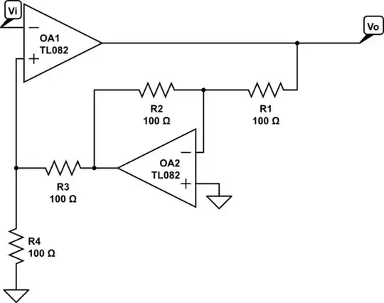
Look at OA2's circuit in isolation to OA1: -
Regard Vo as an input (because that is what is is) and the junction of R3 and R4 as the output
Can you "show" that the voltage at the junction of R3 and R4 is -Vo * R3/(R3 + R4)
Can you see that OA2's circuit is applying feedback to OA1?
Because the feedback voltage formula has a negative sign (the one in front of Vo above) AND it feeds back to the non-inverting input of OA1, does this tell you that it is negative feedback? It is negative feedback!
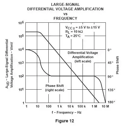
Smallprint: As an acedemic exercise to demonstrate negative feedback this is OK but in the real world, at frequencies approaching the unity gain point on the TL082, its inherent phase shift (and most op-amps) approaches 90º and, because one TL082 is applying feedback around the other one, the combined phase shift will be 180º and this then becomes positive feedback and the circuit will likely oscillate: -