If you have a purely resistive load in series with your inductor, and provide a path for the current to return when the switch is turned off, you should see the behaviour you expect. The energy stored in the inductor's magnetic field will bleed off through the resistor until the field decays.
simulate this circuit – Schematic created using CircuitLab
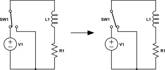
However, it's likely you're simply opening the switch to turn off the voltage, leaving no low-resistance loop for the current to return. When you open the switch, that switch now has two distinct terminals with different charge, separated in space by a dielectric. What component consists of two terminals separated in space by a dielectric?
In other words, when you open the switch, the circuit (left) becomes the circuit (right).
simulate this circuit
Now, you have a series RLC circuit. The magnetic field in the inductor continues to move charges, and those charges build up on the inherent "capacitor" in your circuit. As energy bleeds from the inductor, it builds up in the capacitor, until all the energy in the circuit is now stored in the electric field of the capacitor -- which then starts driving current through the inductor the other way.
The capacitor terminals equalize as their charges move through the inductor, but this builds a magnetic field, which continues to pull charge from the capacitor and charges it again, this time with opposite polarity. As the capacitor voltage becomes more negative, the energy is transferred from the inductor, until the inductor is "empty" and the capacitor is "full".
But then the capacitor starts to discharge again...
Through each cycle, the resistance in the circuit converts some of the energy to heat, and the oscillations eventually die out.
The actual characteristics of the oscillation -- e.g. the period, the amplitude, the settling time -- depend on the specific inductances, capacitances and resistances in your circuit, including parasitic inductance, resistance, and capacitance inherent to all components and your breadboard.
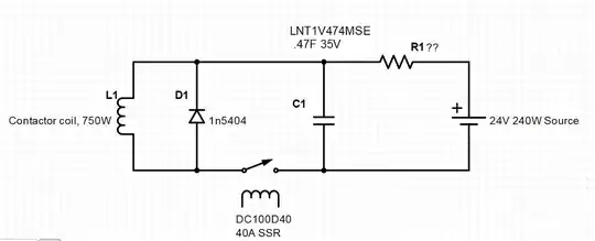
In real circuits, designers will often add a flyback diode, connected antiparallel to an inductive load. This provides a low-impedance return path for an inductor, such that when it is switched off, the inductor's magnetic field will not induce damaging ringing or voltage spikes. The diode is sized to dissipate the expected current as heat without overheating or burning out.
Flyback diode circuit:
simulate this circuit

