2

I am new to electronics and am trying to figure something out:

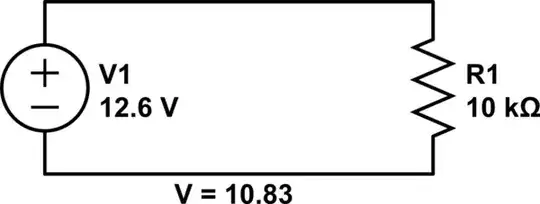
I have a source putting out 12.6V and an unknown current. I know that I can calculate current by finding the voltage drop over a resistor.

schematic

simulate this circuit – Schematic created using CircuitLab

V = IR, so a drop of 1.77V = I * 10kΩ; I = 0.000177A

However, this is a VERY low number, and also I know that I can attach a 12V fan to this circuit which draws 70mA (0.007A), so the circuit must have at least that much current.

Is there some basic law of electronics which I am not understanding, or are my calculations incorrect?

vsams14
  • 23
  • 1
  • 4
  • 3
    Yes, there is something missing in the analysis. Actually there is too much in the analysis. The voltage drop across the resistor will be simply be the voltage you are putting across it, i.e. 12.6V (or 12,6 in your numeric language :) – angelatlarge Apr 07 '13 at 04:30
  • The issue here is probably coming from the term "voltage drop". If you measure 10,83 V at the resistor then your are either losing voltage to your cabling(probably not at 1ma) or you have a battery that is very near end of life and sagging a little. Your voltage "drop" on the resistor is how much the voltage changes across the resistor, not how much it changes getting their. So 10,83/10k is .00183 A or 1.83 mA, which is reasonable for a 10k resistor. – Kortuk Apr 07 '13 at 04:47
  • so, for 1,77V drop, that is happening in your cabling or battery, so if you take that drop with the current you re calculating you can determine the resistance of the cabling+series resistance of battery that is being placed with R1. I would write an answer, but someone with pictures would make a much better job then me. – Kortuk Apr 07 '13 at 04:54
  • @angelatlarge, you are right. the voltage across the resistor will be the same as there is only one load, so the current will be I = V/R, I = 12.6V / 10K = 1.26mA. – David Norman Apr 07 '13 at 05:19
  • It might help if I explained this better: This measurement is from the +12v rail on a molex connector connected to my computer's PSU. There is absolutely no reason for the current to be in mA here. Sorry for the commas instead of periods. I'm used to writing like that. Assuming all I have at hand is several resistors and a voltmeter, how can I determine the original current? I don't have an ammeter at the moment... – vsams14 Apr 07 '13 at 05:48
  • Yes, you can measure current as a voltage by using a resistor, but can you tell us what exactly you are trying to measure, and why? It's difficult to tell what you are trying to do, which makes answering this question a bit like going after a piñata – angelatlarge Apr 07 '13 at 06:07
  • 1
    @vsams14 I believe you might have some misconceptions about what voltage and current from a power supply are. [this question is very detailed and might help you](http://electronics.stackexchange.com/questions/34745/choosing-power-supply-how-to-get-the-voltage-and-current-ratings). If you are just asking if your power supply will work for this fan, if the fan is designed for a 12V supply you are 95% fine. – Kortuk Apr 07 '13 at 06:25
  • I'm doing some modding and wanted to add custom LEDs. They run off of 3.8V but I have to connect them to the 12V rail. I wanted to calculate how much resistance I needed to lower the voltage as necessary, realised I hadn't a clue how much current was on the wire, and went off on a tangent. I realise that I can just hook up resistors until the voltage reaches 3.8V and not care about the current. In fact, I already have and know I need 70k to do so. But I'm still curious how much current is actually flowing through the wire... – vsams14 Apr 07 '13 at 07:23
  • So from the above article, I understand that even though there can be up to say 15A pushed through the wire, only as much as the circuit needs (1.26mA) will actually be delivered. Therefore, when the 70mA fan is connected, 70mA are pushed through, when the LED is connected, the required current for that is sent. In which case, how do I go about actually calculating how much I need to raise the resistance of the circuit? Again, I know I can just guess and check, but I want to be able to calculate this, and also better understand the whole concept... – vsams14 Apr 07 '13 at 08:48
  • Maybe also have a look at [Kirchhoff's laws](http://en.wikipedia.org/wiki/Kirchhoff%27s_circuit_laws#Kirchhoff.27s_voltage_law_.28KVL.29), which tell us that the sum of voltages in a loop must be zero. For your case this implies that the voltage across the voltage source and the voltage across the resistor must be of equal absolute value at any time. If there are more resistors, or for example a fan's motor, in series the total voltage is distributed over them so that the sum of all voltages will be zero again. – JimmyB Apr 07 '13 at 10:38
  • "the required current for that is sent" - Nooooo! Stoooop! :) Don't imagine the current to be "sent" but rather to be "drawn" by the devices. You should be safe to assume that your power supply *can* deliver unlimited current for your use case and will keep the voltage of 12V constant, and putting your LED directly to the 12V rail will turn it into smoke in no time! – JimmyB Apr 07 '13 at 10:48

1 Answers1

0

The question, taking into account comments by the OP, seems to boil down to this:

  • How to calculate the current limiting resistor needed for operating an LED with 3.8 Volt forward voltage rating.

LEDs are current-based devices, not voltage based. In other words, the design parameter for a driving circuit is, how much current should be allowed to pass through an LED. This current limiting is frequently done by putting a resistor in series with the LED (one for each LED if several are to be used in parallel).

The current rating of the LEDs is not stated in the question. Since many common LEDs are typically rated for 20 or 30 mA, assuming 30 mA (0.03 Amperes) for the purpose of this answer.

  • Supply voltage = 12.6 Volts
  • Nominal voltage drop across LED = 3.8 Volts
    (this nominal value would apply for nominal current passing through the LED, and both values should be taken from the LED datasheet)
  • Therefore, voltage that must be dropped across the resistor = 12.6 - 3.8 = 8.8 Volts
  • The current through every component in a series circuit must be equal, hence, applying Ohm's Law V = I x R to the above voltage gives us
    • R = 8.8 / 0.03 = 293.33 Ohms

The next higher commonly available resistor value of 330 Ohms would work well - Connecting one in series with each LED fed from the 12 Volt power rail should work fine. The higher than calculated resistor also increases the margin of safety by slightly reducing the current through the LED, without perceptibly reducing illumination.

However, there is another twist to this tale: The power rating of the resistors used.

  • By Watt's Law, P = V x I = V^2 / R.
  • For 8.8 Volts to be dropped across 330 Ohms, P = 0.23467 Watts
  • This is pretty close to a quarter watt, one of the commonly used resistor power ratings. Therefore, for a margin of safety, a higher wattage resistor is suggested.
  • In conclusion: Use a half-watt, 330 Ohm resistor in series with each LED in your circuit.
Anindo Ghosh
  • 50,188
  • 8
  • 103
  • 200
  • Your 3.8V drop over an LED may be a little too high. White LEDs usually won't have more than 3.3V, and 3.8V will fry them immediately. - And maybe it's worth mentioning that LEDs of different colors will have significantly different Vf. – JimmyB Apr 07 '13 at 10:50
  • @HannoBinder The 3.8 Volts figure came from OP's comment, "*...wanted to add custom LEDs. They run off of **3.8V**...*". Also, I have a bunch of UV LEDs inside my PC cabinet, and they're rated 3.8 Volts as well. – Anindo Ghosh Apr 07 '13 at 11:41
  • Ok, didn't think of UV for illumination, but for 'modding' I guess they're not uncommon :) – JimmyB Apr 07 '13 at 11:49