5

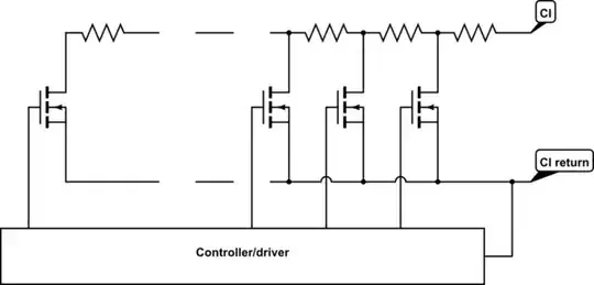
We have to interface with a device that is expecting a chain of 34 Ω resistors with switches connected to the input pins as shown below.

There is no information on the internal schematics of the device, but there is 10 V present on the open circuit and when shorted the current is limited to 5 mA. The documentation mentions "maximum input voltage 34 V", which is weird, since we are not expected to supply voltage to those pins.

enter image description here

My first thought was to simply emulate the suggested circuit with analog switches (like ADG715) and a bunch of resistors. Then I thought of digital potentiometers (like AD5254), that do not need resistors.

The problem, however, is that all these chips have analog voltage limits pretty close to their digital supply lines. So, it seems I need either a way to add a high-voltage-tolerant output stage to the digital pot, or use a completely different approach, like a DAC + VCR (voltage controlled resistor). Unfortunately analog circuits are still my weak spot; I'm not sure I can design a FET-based linear VCR properly.

Any other options I have missed? I should also mention that simplifying the circuit and reducing cost are important to us.

ocrdu
  • 8,705
  • 21
  • 30
  • 42
Maple
  • 11,755
  • 2
  • 20
  • 56
  • 1
    What do you know about the voltage that the device applies? Is it AC or DC? Maximum current? Is this some kind of automotive gauge? – Spehro Pefhany Dec 21 '22 at 19:46
  • @SpehroPefhany The _measured_ voltage is 10VDC. The documentation mentions maximum input 34V, but I don't know what they mean. The device is powered by 24VDC, so this does not look like pull-up to power input. Could be current source or could be their internal working voltage. Maximum current when shorted out is 5mA. This is not a single device actually, this is wheelchair power system with several modules having control inputs for external switches. – Maple Dec 21 '22 at 19:56
  • So your schematic is wrong if it provides current, which makes any answer pointless. – StainlessSteelRat Dec 21 '22 at 20:05
  • 1
    @StainlessSteelRat I have no idea what you mean. Care to elaborate? It is not _my_ schematics. It is the circuit suggested in device documentation. – Maple Dec 21 '22 at 20:08
  • 2
    We don't really know enough about the circuit, I think. It's possible a simple 0-3V voltage could replace all that stuff if it could sink the 5mA. The resistances are a bit low for analog switches that can handle >10V, and much worse if you try to put them in series rather than as shown. – Spehro Pefhany Dec 21 '22 at 20:12
  • @SpehroPefhany "don't really know enough about the circuit" - yes :( On top of that, common digital pots have wiper resistance comparable to 34 Ohm and over 5k total range, requiring at least 1024 taps to get correct steps under 700 Ohm. – Maple Dec 21 '22 at 20:21
  • @SpehroPefhany AD/Maxim has some high voltage pots, e.g. [AD5290](https://www.analog.com/media/en/technical-documentation/data-sheets/AD5290.pdf). They have all the usual problems, but I am thinking... can several of these be used in parallel, like normal resistors? That would deal with high wiper resistance and even more - should allow me to find combinations to get precise total resistance – Maple Dec 21 '22 at 23:40
  • @Maple Perhaps that will work, connected as parallel rheostats, provided the voltages are okay and the current is actually limited to 5mA. Absolute Maximum continuous wiper current is 5mA. – Spehro Pefhany Dec 21 '22 at 23:54
  • If you are able to experiment it might be worth a shot to put a single mosfet on the line and PWM switch that at a sufficiently high frequency to see how the device responds to that. It might read different switch states at different duty cycles. If it works it would be a total hack, and you'd need to check if it works the same across multiple devices. But it would be a minimal number of components. – AVee Dec 22 '22 at 21:58
  • @AVee Sorry, I wouldn't even try this on wheelchair control system. – Maple Dec 22 '22 at 22:00
  • What is your question: you want to replace the resistors or the switches? I'm assuming you want to emulate the possible different switch settings under software control. Or something else? – spuck Dec 22 '22 at 22:01
  • @spuck I want to make an interface from MCU to the device that normally uses button pad with resistors as input device. Preferably with few components. I have listed couple options I came up with. My question is literally about other possible interface options. – Maple Dec 22 '22 at 22:57
  • How does the device under control respond when multiple buttons are pressed? Does it ignore all buttons, or respond only to the first one in the chain? Do you have a common ground available you can reference a generated voltage against, or must it be floating (i.e., no common reference)? Do you need to implement all 17 switches, or only a few? – spuck Dec 22 '22 at 23:19
  • @spuck The device has no way of knowing when multiple buttons are pressed. Two input pins should be treated as the only pins available. At least 15 switches. – Maple Dec 22 '22 at 23:42

4 Answers4

5

How about this idea?

schematic

simulate this circuit – Schematic created using CircuitLab

Choose some suitable MOSFET and, as long as CI is always positive relative to CI return, it'll work. If CI can go negative, you'll need bidirectional switches instead of MOSFETs, for which you could use certain types of solid-state relay or SSR-type optocoupler.

Hearth
  • 27,177
  • 3
  • 51
  • 115
  • This should work. Although the goal was to reduce a number of components, not increase it. We have 4 channels, so 68 FETs and 68 resistors would be quite expensive, even if arrays were used. – Maple Dec 21 '22 at 19:22
  • @Maple Depending on precision needed, I can find 34 Ω resistors in bulk for [less than $10 for 5,000 of them](https://www.digikey.com/en/products/detail/yageo/RC0402FR-0734RL/5280988), and [suitable MOSFETs for $16 for 100](https://www.digikey.com/en/products/detail/micro-commercial-co/SI2318A-TP/9655963). That's not that expensive in my book. You'd be paying more on the circuit board (say $150 from a cheap fab) than on the parts. – Hearth Dec 21 '22 at 19:31
  • You are right, the cost would not be a factor in mass production. But the PCB size would grow unnecessary. I was rather hoping for some kind of "current mirror" type of circuit, only with voltage input on one side and variable resistance _independent of the applied voltage_ on the other. Then one 4-channel DAC chip can drive four such stages – Maple Dec 21 '22 at 19:46
  • Oh, and yes, CI is always positive relative to return. In most devices the return is internally connected to ground (24V battery "-") either directly or via fuse, as far as we can tell from documentation. – Maple Dec 21 '22 at 20:12
5

One option to cut down on the number of switches and resistors would be to use a binary chain like this:

schematic

simulate this circuit – Schematic created using CircuitLab

Start with all switches closed, then open them in a binary pattern to add in resistance. For example instead of 6 x 34\$\Omega\$ resistors to get 204\$\Omega\$ you would open SW2 and SW3.

The last resistor is 34\$\Omega\$ because the original has 17 steps, so you need one extra 34\$\Omega\$ step than a 4 bit arrangement would give, but it could also be 544\$\Omega\$ to get even more steps.

GodJihyo
  • 17,628
  • 1
  • 16
  • 45
  • Wow, very neat! Did not think of this. – Maple Dec 21 '22 at 19:58
  • @Maple If you use a micro and digitally controlled switches you can just program the correct patterns to open them for any multiple of 34 ohms. – GodJihyo Dec 21 '22 at 20:01
  • 1
    Small downside to this one is that the switches now have to be floating; you can't use a simple FET driver for them as any switch could be at any voltage from 0 to 34 V. If that's fine (like if you're using optorelays), this is probably better than my suggestion, but it may mean using a few more parts than it looks like here. – Hearth Dec 21 '22 at 20:02
  • Yes, I've noticed that part. It was original problem with both switches and pots. But if the number of components in the high-voltage output stage can be reduced to this then optocouplers or reeds can be a viable solution – Maple Dec 21 '22 at 20:06
  • 1
    @Hearth Yeah, that's the one thing with this, you need to use something that acts like a real mechanical switch, such as a relay. – GodJihyo Dec 21 '22 at 20:07
  • Photo FET optocouplers would be suitable for this. – jpa Dec 22 '22 at 18:38
  • @jpa this solution requires very low switch resistance, otherwise getting correct total would be impossible. FET couplers typically have 100-400Ohm RDS(on). – Maple Dec 22 '22 at 21:43
  • @Maple Hmm, you are correct. – jpa Dec 23 '22 at 06:36
2

As for Digital Potentiometers, Microchip have some High-Voltage versions which have an analogue supply voltage of 10V to 36V, in the High Voltage (>10V) Digital Potentiometer Products.

E.g. a MCP41HV51T-502 with 8-bits and a 5 k\$\Omega\$ resistor will give a Step Resistance of 19.6\$\Omega\$. Some issues with using a Digital Potentiometer directly could be:

  1. Finding a step size which allows all 34\$\Omega\$ steps to be reliably generated, allowing for tolerances.
  2. At reset how the initial resistor string value is set and what effect that has on the device being controlled. This Microchip range are all have Volatile memory. At reset they default to a mid range resistance setting.

Also, since the application is for a wheelchair power system, are there any functional safety requirements which need to be met?

Chester Gillon
  • 474
  • 3
  • 4
  • Yes, I have found those chips myself too, as well as some 30V from AD/Maxim. And yes, there is the problem with getting the value right. Most chips begin at 10k or 20k, and very few of them have 1024 taps. One solution I've mentioned in the comments would be to put two (or more) pots in parallel and use them to fine-tune combined resistance. Dual/Quad chips are great for this. There are dozens of safety requirements, of course. I am working on those separately, trying to keep the question straight on one point only. This usually yields better results here. – Maple Dec 22 '22 at 14:26
  • Also, regarding safety, these ports are designed for user-operated button pads. The golden rule of any human interface is that if anything can be pressed in a wrong time, it _will be_ pressed eventually. So, the safety is implemented on the device side, giving us an opportunity to properly initialize interface. – Maple Dec 22 '22 at 14:49
  • I did some calculations and a couple 5k Microchip would have worked. They skip first band due to high wiper resistance but the rest fits nicely. Unfortunately they are impossible to source nowadays. The AD/Maxim chips begin at 10 or 20k and cannot be used. – Maple Dec 24 '22 at 15:44
1

Similar to GodJihyo's answer, but making it possible to use simple logic-level MOSFETs for control:

schematic

simulate this circuit – Schematic created using CircuitLab

The idea is to have a +15V supply, which is at least Vgs higher than the maximum voltage put out by the device (10V). I'm assuming logic-level MOSFETs that turn on at 3V and can take a 20V gate voltage (for example PJA3404).

Normally R1-R3 pull up the gates of Q1-Q3, resulting in a direct short. Device sees 0 ohm resistance, equivalent to S1 being closed.

If e.g. IO0 is turned high, Q4 pulls down the Q1 gate and the device sees 34 ohm resistance. Turning on all of IO0, IO1 and IO2 will result in 34 + 68 + 136 = 7 * 34 ohm resistance.

This schematic can be expanded to any number of bits. If infinite resistance is needed as option, one extra MOSFET should be added between the lowest resistor and ground (it can be driven directly by IO pin).

jpa
  • 6,804
  • 17
  • 32
  • I have to use GPIO expander to control a bunch of signals anyway. If I can find one with OD outputs that can tolerate 15V, then I can drive the gates directly. It would make this solution quite compact – Maple Dec 22 '22 at 21:32
  • I've accepted @Hearth answer because it was most cost effective and we already implemented it in a working device. However I'll keep this in mind because it is actually easier to interface with MCU, since digital value written into IO port will set port pins into binary combination suitable for direct driving of the FETs, no decoder necessary. Thank you. – Maple Aug 31 '23 at 03:50