6

I have an analog circuit that takes a ±15 V DC voltage and some input signals, does some things to the signals and outs an analog signal via an op-amp. I would like to limit the output voltage to ±10 V to protect circuitry down stream. I am considering using a rail-to-rail op-amp, supplied with ±10 V to do this. Is there any reason not to do it this way? Or should I just stick with diodes?

Sorry if this is a duplicate question. I searched the site, but couldn't find this exact question.

Update:

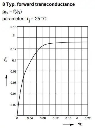
Thanks for all the great responses. At least one person asked for a schematic. Below is partial schematic showing the last part of the circuit (there could be IP in the rest of the schematic). w123 is the signal input. It is averaged through an active RC filter and is sent to three op-amps with different gains (final amplification to be determined. May be 1x-100x). The idea being that we can select an appropriate gain based on the signal (kind of like selecting a magnification on a microscope). When the signal is low, the high-gain output can be used, when it is high, the low-gain op-amp can be used. I don't plan on using the signal close to the rails: I just need to limit it to protect a multiplexer and an ADC down stream (partial schematic below).
enter image description here

njs
  • 277
  • 1
  • 7
  • 4
    It might make more sense to say that you would like to clip a _voltage_ rather than a _circuit_. – JYelton Dec 20 '22 at 18:51
  • 1
    Rail-To-Rail Op-Amps can be somewhat non-linear towards the ends of the rails. So if "precision" is required i would go with +/-12V supplys and clip the voltage with a zener to like +/-10.5V. A little series resistance can be used to further protect the downstream-devices internal protection diodes. If "precision" clipping is required i would go with some sort of op-amp biased diodes. – ElectronicsStudent Dec 20 '22 at 19:06
  • 1
    *I searched the site* The circuit you're looking for is called a voltage clamp, and there's a bazillion of duplicate answers on this site. Once you know the name of what you need, the problem is solved :) – Kuba hasn't forgotten Monica Dec 20 '22 at 19:47
  • @ElectronicsStudent, thanks for the comment. I did make a circuit with diodes on the output, at one point, but I saw a ton of oscillations near the 10V-limit, and it made me shy away from that solution (maybe I picked the wrong diode). Also, the circuit will kill the diodes if I don't add a current-limiting resistor to the output as well, which creates a voltage divider with the next circuit, which makes estimating the gain more difficult. – njs Dec 20 '22 at 20:12
  • @njspeer The stability issues could be caused by too big in value feedback resistors in the negativ path. They form an RC circuit - the diode should matter little. But: I also had some issues with high bandwith signals and so on. This is why i commonly allow the 200-700mV extra drop accross the diodes just to have some headroom on the amplitude. Good multimeters will have at least 10Meg and a ossiciloscope will have 1Meg of input resistance with ||10pF. So using a 1k resistor to limit the circuit to 10mA wont do any significant harm. Otherwise you can use a voltage follower in series. – ElectronicsStudent Dec 21 '22 at 06:54

4 Answers4

7

If you want a simple voltage clamper try this dual zener circuit: -

enter image description here

Image from here. However, if you need precision clamping read on...

This circuit provides a precision voltage clamper. As shown below it has a positive clamp voltage of +5 volts and a negative clamp voltage of -1 volts but, this can be easily adjusted: -

enter image description here

  • U2 clamps the positive peak to 5 volts
  • U3 clamps the negative peak to -1 volt

The clamp values can be adjusted by V3 and V4.

Image from this answer. Another example of basically the same circuit can be found here: -

enter image description here

Andy aka
  • 434,556
  • 28
  • 351
  • 777
5

I am considering using a rail-to-rail op-amp, supplied with ±10 V to do this. Is there any reason not to do it this way?

It could work and could be a perfectly OK way to do it. There are two things I can think of to consider.

  1. You have to somehow be sure that you won't exceed the allowable input voltage range for the op-amp. Typically op-amps do not want to see input voltages exceeding their rails. Sometimes the range is more restricted than that. So check your datasheet.
  2. Saturation effects. If the op-amp is driven hard so the output slams into one of the rails, some of the internal circuitry may be in deep saturation, and it may take a bit of time to recover when the input signal comes back in the normal range (the range that calls for the output to be within +/- 10 V).

I am not too sure how much of a problem 2 will be with modern CMOS rail-to-rail op-amps. I am thinking it won't be much of a problem. But it is something to keep in mind.

So I say go for it.

user57037
  • 28,915
  • 1
  • 28
  • 81
  • Thanks for the comment. the inputs will not exceed the allowable input range. And I don't plan on using the signal too close to the rails. I just need a nice clean way to limit the output to ±10V. – njs Dec 20 '22 at 20:15
5

Using a rail-to-rail op-amp is a good idea -- but don't bother making extra supplies, use the 15 already available. This gives a 15V output range, too much, right?

Simply reduce the output with a 1:2 resistor divider (e.g. 4.99k + 10k). (You will need an extra 33% gain going into this limiter, of course.) Then add a second op-amp as voltage follower (buffer). If the output is feeding a high impedance, the buffer can even be omitted. Or if the load impedance is a fixed resistance, it can be combined as part of the resistor divider.

Tim Williams
  • 22,874
  • 1
  • 20
  • 71
3

I frequently use the following circuit to clip +/-5V external signals to a "human controllable threshold".

The circuit is configured to x2 amplify the threshold signal (V3, in your case +5V) and then provide the inverted output as well. This gives the rails: Threshold2 and Threshold(-2) Then, the diodes limit the signal voltage to +/-(Threshold*2 + V_DiodeDrop).

CAUTION: Can your op-amp source/sink the required currents to act against the signal source impedance?

I usually want the 200-700mV (There are some ~50mA shottky SMD-diodes out, which only have 100mV drop. I usually go with the cheapest what ever diode rated for the voltages and currents involved) extra range on the signal. If you dont want it, you can just connect the op-amp feedbacks "before the diodes".

NOTE: Usually the threshold-voltage (V3) is generated in my designs via a HMI rotary switch providing a switch-able resistor divider. This is the reason, i invert the already amplified signal and do not use a x(-2) op amp (Lower imput impedance changing the equation for the voltage divider!)

NOTE: This implementation has some issues with very high-frequency signals due too the limited slew-rate. But 100kHz bandwith is not an issue with common parts - I mainly use it for sensor signals or control signals within 10kHz bandwith.

PROS: The actual signal is not feed through an extra op-amp (introducing non-linearity, delay, phase-shift, etc.) and is only affected mildly by the diodes in normal operation (Signal-source has source impedance, but leakage-current thorugh the currents is somewhat low!). Also, by not using a "rail-to-rail" op amp, non-linearty and saturation effects on the signal are avoided - this is can be important as "rail-to-rail" can be an issue even with modern cmos-amplifiers.

CONS: You need extra components, extra board space, extra validation steps and so on. You can only limit signals with a fairly high source-impdance with common op-amps.

Circuit and simulation

ElectronicsStudent
  • 2,746
  • 5
  • 18
  • The slew rate of the op-amps doesn't really figure here: the diodes act as switches, the op-amps are just voltage buffers. The accuracy of the circuit is limited by the variable current through the diodes, and thus variable effective clamping voltage that's dependent on the input voltage. – Kuba hasn't forgotten Monica Dec 20 '22 at 19:36
  • Expect when the signal crosses the clamping threshold and the op-amp needs to jump "a single diode-drop in current-sink capacity" in dt=0 to discharge the diode capacitance - which is limited by the slew-rate to dt != 0 thereby introducing a "step" in the signal. – ElectronicsStudent Dec 20 '22 at 19:39
  • The voltages on the op-amp outputs are constant. No op-amp needs to "jump" anything. U1 is a x2 buffer, U2 is a -1 buffer. You could replace the op-amps with a couple batteries :) The change in load current is rather gradual as the clamp diodes start to conduct, and most op-amps will deal with that just fine, without aberrations. For ultimate in performance, the clamps should cede AC impedance to a decoupling capacitor, i.e. they should only be in-loop at "low" frequencies. But that's of no big importance due to the rather large errors introduced by the diodes themselves. – Kuba hasn't forgotten Monica Dec 20 '22 at 19:42