I'm an embedded software developer and am trying to up my electronics and board design knowledge. As a good first exercise I made a ZVS induction heater. project link
Once assembled I was happy to see that it worked! The oscillation is happening just fine and I can heat up metal. But when I cranked up the voltage to 8 volts or so (my initial tests were at 4-5 volts), one of my diodes let out the magic smoke. Apparently they're getting really hot!
It concerns the D1 and D2 diodes. They are the UF4005, but I've also tried the FR107 (of which I know it was used in another similar design) with the same results.
So now the question is why these diodes get so hot.
I could probably blindly copy one of the designs on the internet, but then I wouldn't understand what is going wrong.
I measured the voltage across one of the diodes (at a system lower voltage) and got the following result. (Green is voltage across diode, yellow is voltage across the big inductor and capacitors)
This voltage looks really weird. Why does it stay high for so long when the voltage across the inductor switches? This is the only thing I could probe that looks really weird.
The only thing I could find that could be wrong is the component choice for L1 and L2. Instead of winding my own coils I bought them. It seems that these inductors can get saturated. I don't know how I could measure that in this circuit, so I'm not sure if that's happening. But say that it does happen, then I can't see why that would overheat the diodes. I would just waste more power than necessary, right?
Anyways, these are the components that I think are relevant:
- D1,D2: UF4005
- Q1,Q2: NTP067N65S3H
- C3,C4,C5,C6: MKS4O136806F00KYSD
- L1,L2: 2300HT-221-V-RC
The zener diodes don't do anything yet because the voltage is still too low.
The oscillation happens at ~40khz.
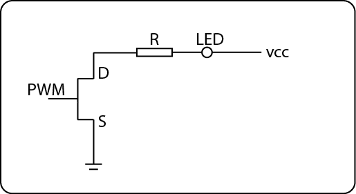
As a reference, here's a schematic of the same concept in a different form:


