1

I've been researching RS485 hotplug protection for a while and come up with the following solution. The reason is that I burned two custom Arduinos, after further investigation it turned out the GND pins of the Molex connector of the hub were not properly seated and made contact very late. So my intention is to add a delay + ramp on the +12V, and I have also added the RS485 protection from https://www.mouser.com/new/analog-devices/adi-bourns-rs-485-transceiver-protection/

However, I have very little electronics experience and need help verifying that all is good before I get PCBs made and assembled for this.

Project is available here

Relevant updated parts from old design

+12V delay and ramp:

enter image description here

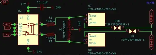
RS485 Protection from Mouser.com:

enter image description here

Full Schematic:

enter image description here

PCB:

enter image description here

winny
  • 13,064
  • 6
  • 46
  • 63
Maciej Swic
  • 363
  • 2
  • 11
  • Your layout does not look like it's been drawn by someone with very little electronics experience. Is this a two-layer design or are the inner layers hidden? In general, I would recommend a four-layer board with solid ground and Vcc planes on the inner layers. – winny Dec 15 '22 at 12:28
  • @winny no, it's a 2 layer board as 4 layers is, well, 4x the price unfortunately. My previous 2 layer design works fine without the voltage ramp and rs485 protection devices. But i will consider it for the future nonetheless. – Maciej Swic Dec 15 '22 at 12:33
  • I see. If it works and passes EMC with two layers then no issues. If you have EMC problems down the line, layout would be my first thing to look into. Do you get any DRC errors in your layout? – winny Dec 15 '22 at 12:44
  • Thanks, no DRC errors, I'm using JLCPCB and tried to mirror their capabilities manually as there is no profile to import in KiCad like Eagle, and it passes and previous boards were produced without issues. Did i get the PMOS polarity correct please? They still confuse me. – Maciej Swic Dec 15 '22 at 12:50
  • Which PMOS? I don't see any in the schematic. – winny Dec 15 '22 at 13:02
  • @winny U6, the topmost part in the first image. https://datasheet.lcsc.com/szlcsc/1912111437_HUAYI-HY15P03C2_C123687.pdf – Maciej Swic Dec 15 '22 at 13:11
  • Oh! No wounder. Please refrain from drawing schematic symbols as their package equivalents. This hinders schematic review. Please draw it as a PMOS. – winny Dec 15 '22 at 13:16
  • @winny Sorry, I imported the part with a script from LCSC because it includes the footprint and 3d model. The pins are labeled S, D & G though. – Maciej Swic Dec 15 '22 at 13:19
  • Just a quick sanity check - what does protecting the RS-485 bus help if it was the MCU that blew up through the TXD and RXD pins, not the MAX485? MAX485 should handle -8/+12V on bus pins just fine. – Justme Dec 15 '22 at 15:54
  • @Justme The TXD/RXD go through the MAX487. So if i protect the A/B lines of the bus, it won't fry the AVR? Maybe the MAX487 handles it fine but not the AVR. Or am i completely lost here? I'm sure the issue was GND making contact after +12V and A/B because the GND pins are clearly a couple mm deeper into the connector. – Maciej Swic Dec 15 '22 at 18:31
  • The TXD and RXD go to connector too. So even if they do, they are unconnected? And yes, RS-485 transceivers can sit on the bus unpowered. If it could not handle that, the MAX485 would be the one to fry. Well, either way, there was no diodes to protect the regulator. The slew limiter should do the trick to protect it. – Justme Dec 15 '22 at 19:21
  • @Justme They go to LEDs in the hub. TXD/RXD to current limiting resistor to LED. But i suppose maybe thats a ground path as well? Could that have also have fried it? Don't really understand how this works thats why im here. Should i get rid of the RS485 protections and just stick with the voltage ramp? – Maciej Swic Dec 15 '22 at 19:53
  • @MaciejSwic Yes well looking at single component of the whole system does not help. Knowing the whole system what is on each pin would help. So the TXD and RXD go through cable and have a remote LED, resistor, and connects to remote GND? Are grounds connected together anywhere else? What's on screw terminals? – Justme Dec 15 '22 at 20:40
  • @Justme The TX/RX are only for activity indicators. They connect to GND on other side of cable but GNDs are tied together except for that unfortunate situation with the cable. Maybe i should get rid of the indicators alltogether? Not really important. On the screw terminals i mostly have switches, pots and rotary encoders. Occasionally a servo or an LED. – Maciej Swic Dec 16 '22 at 06:24

0 Answers0