11

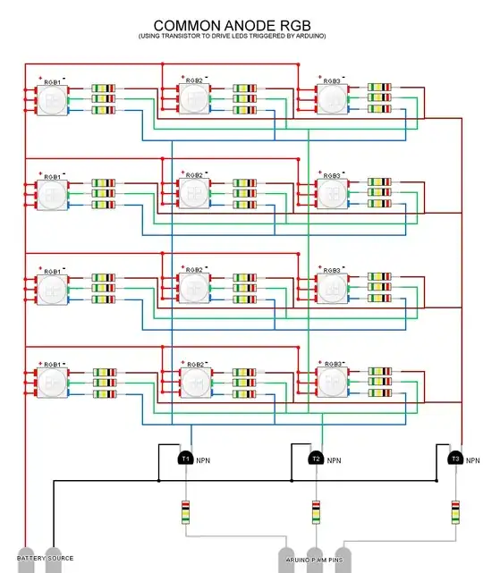
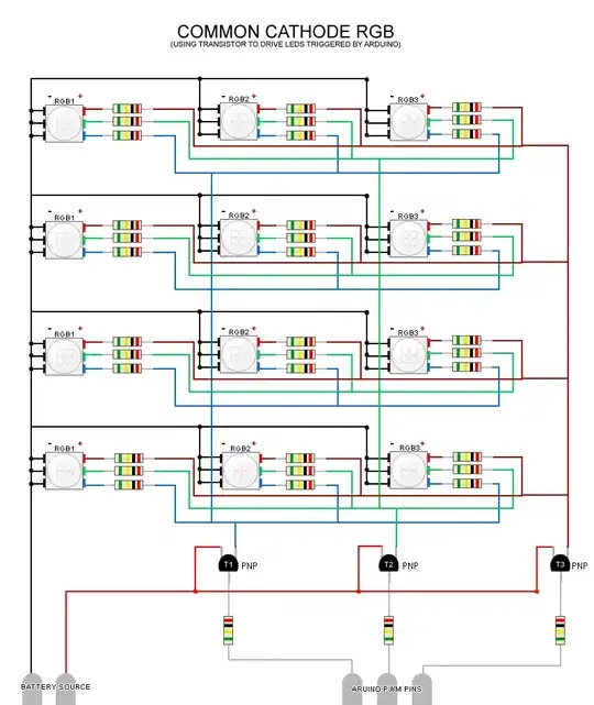
I currently have an anode RGB connected to the 11, 10, & 9 PWM pins on my arduino. However I would like to add 3 more LED's to my project, but I don't want to necessarily take up every single PWM pin (I still want to attach a shield). Is there a way for me to hook up all 4 LED's & still be able to only use a minimum number of pins? Keep in mind that I do want to use all 12 resistors for the 4 LEDS. Oh and all the LEDs will do the exact same thing (They all will be red, and all turn blue, etc) if that helps.

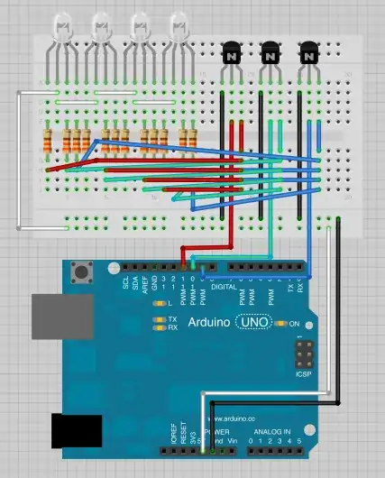
Here's how my board looks right now:

enter image description here

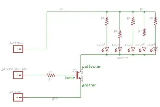
I have three NTE123AP transistors I can use for this project.

P.S. I attached the .fzz file so that if any of you would like to edit the schematic image, it would be super easy. In fact that would be better since I'm new at this, and it would be easier to follow! : )

VAlexander
  • 191
  • 1
  • 2
  • 11
  • Individual Control or all with the same color (All Red at the same brightness, or essentially 12 individual leds?) The former could be done just with transistors, while the latter would require a shift register or i2c/spi expander or led driver ic. – Passerby Apr 06 '13 at 00:31
  • Basically I want 4 RGB LEDs and they all will do the same thing. For example I want to sync sound with light. So when Track 1 plays all 4 LEDs will glow red, and when Track 2 plays they will all glow purple, If Track 3 and they'll glow blue, etc. Hope that helps! I mentioned 12 resistors, because similar to the image I posted, I want a resistor for each led pin, because I don't want to sacrifice brightness. Hope that helps! – VAlexander Apr 06 '13 at 00:40

2 Answers2

14

Fairly simple. Just using npn transistors. Duplicate per color channel.

enter image description here

Your transistor can sink up to 600mA continuously. At 20mA per led, 4 per channel, that's only 80mA. That's more than enough.

But make sure your power supply can support that. 80 * 3, that's 240mA on the leds alone, not including the rest of the arduino, the transistor base, anything else you are using.

OP Provided a Fritzing Diagram of the answer as well: enter image description here

Passerby
  • 72,580
  • 7
  • 90
  • 202
  • @CloudyDays 3 channels (One Red, One Green, One Blue). 4 Leds. Sorry, I don't use fritzing, but simply, Battery Plus is VCC, Arduino_PWM_PIN is the same one you used, and Battery - is Gnd. – Passerby Apr 06 '13 at 01:14
  • 1
    @CloudyDays In this case, yes, vcc is 5v. And that setup is mostly correct. First, the transistor, make sure that it matches the base/emmiter/collector pinout of your transistors, not all use the same pinout. And you have all four leds off one resistor (per color). It might work, but that's not the best option. But generally correct. As far as fritzing go, I still think it's a good tool, just like any, but just don't use it myself. – Passerby Apr 07 '13 at 00:23
  • @Passerby thank you so just to clarify, is it best to use a total of 3 resistors overall for the 4 leds, or should I use 12 (in this scenario). Also, do I only need 1 transistor or all 3? – VAlexander Apr 07 '13 at 01:46
  • 1
    @CloudyDays while 3 resistors work, it does not work well. 12 is preferable. And you need all three transistors, one for each color/channel. Otherwise, the red, blue, and green channels would all be the same, so you would be controlling them like a single led (white-ish). – Passerby Apr 07 '13 at 03:42
  • @Passerby Oh I see. Just to make sure I understand it, how's [this](http://s7.postimg.org/7loe8qexn/Screen_Shot_2013_04_07_at_8_43_16_PM.png) now? PS Assuming I accidentally put in the transistor the wrong way (CBE instead of EBC) what can happen? Thank you for all your help! I'm just having trouble understanding what the front and back of the transistors are (Its flat on one side and semi-circle on the other). – VAlexander Apr 08 '13 at 03:47
  • 1
    @CloudyDays That works. Just make sure that the Collector/Middle Pin is connected as well (Right now, nothing connects to it). As for the transistor, the flat part where the writing is, is normally the "front". And if you had connected it ecb, like you had, you could have shorted the PWM to ground, without a load. Possibly blown the arduino port. Connecting it CBE (as in, Collector to Ground), well, not too sure. – Passerby Apr 08 '13 at 04:19
  • So I've finally hooked it up in physical terms, but I've noticed that my rgb colors are acting funny. Could this be because of the type of LEDS? I have anode LEDS. – VAlexander Apr 08 '13 at 06:04
  • @CloudyDays Common Anode LEDS in this setup, are the opposite of your original setup. PWM Logic High/1/On/5v, is on, Logic Low/0/Off/0v is Off. On your original setup, with the pwm pins acting as the led ground, Logic High was off. – Passerby Apr 08 '13 at 06:43
  • @CloudyDays lets talk in this chat: http://chat.stackexchange.com/rooms/8243/arduino-rgb-setup if you need more help, to avoid clogging up the comments – Passerby Apr 08 '13 at 06:54
11

These diagrams/images might be better to visually see whats going on:

COMMON ANODE RGB w/ TRANSISTOR

COMMON CATHODE RGB w/ TRANSISTOR

Side note

@Passerby: Where did you get that schematic image in your post?
Nick Alexeev
  • 37,739
  • 17
  • 97
  • 230
whispers
  • 211
  • 2
  • 2
  • Welcome to EE.SE. Thanks for posting the schematics. As a general rule, questions to other users are posted as comments, rather than answers. It doesn't take a lot of rep to get the commenting privilege. – Nick Alexeev Jun 11 '13 at 22:14
  • sorry not sure how it works here yet.. but thats my image, which is why I asked, cant post images until 10 rep points or something. – whispers Jun 12 '13 at 03:10