I have a few options for the frequency generator side (25-35 Khz). Namely the NE555 or Arduino are some options. These outputs are minimal and I intend to drive the piezo X 4 Vp-p 12 V. Is the MOSFET the best option on this side? Please any information would be appreciated. I am from a electrical background and trying to learn electronics so excuse my ignorance.
Asked
Active
Viewed 110 times
2
-
Can you please provide a datasheet of your piezo? – Jens Dec 12 '22 at 15:43
-
Hi Jens.Description: 51mm Wateroof Piezoelectric Ultrasonic Speaker. Rated Noise Power: 5.5Vp-p. Rated Long Power(Max): 30Vp-p. Rated Frequency: 2.5-60KHz. Can be used in repellers, bird repellers, dog training devices, etc. Specification: Poduct: Piezoelectric Ultrasonic Speaker Material: ABS Rated Noise Power: 5.5Vp-p Rated Long Power(Max): 30Vp-p Rated Frequency: 2.5-60KHz Operating Frequency: 20�5KHz Rated Sensitivity: 100dB Operating Temperature: -20~60 Storage Temperature: -30~70 Diameter: Approx. 51mm/2.01inch Height: Approx. 20mm/0.79inch – Cameron Lee Cameron Dec 13 '22 at 08:49
1 Answers
1
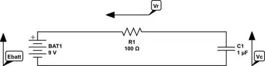
I don't know the capacitance of your piezo, but you can abuse a MOSFET gate driver with one inverted and one non inverted output for a start.
The 12 V supply will provide the required Vpp level at the piezo.
R1 limits the peak current and is just a guess.
Some motor driver chips like DRV8220 can handle these frequencies as well.
simulate this circuit – Schematic created using CircuitLab
Another approach uses a tapped inductor or transformer. The output voltage can be contolled by variations of the signal generator duty cycle, values up to 50% are useful.
However, the resonance frequency of transformer inductance and piezo capacitance should match the input frequency. So this circuit can not be used if a wide frequency range is required.
Do not use this circuit without a connected piezo. High drain voltage peaks can destroy the MOSFET in this case.
Finally an old school CMOS multivibrator with BJT bridge:

Jens
- 5,598
- 2
- 7
- 28