7

I've received a failed switch-mode DC-DC step down converter (part# LTC3631 from Linear). This circuit was driven by a 24VAC transformer which is rectified on the circuit:

schematic

simulate this circuit – Schematic created using CircuitLab

The leads from the transformer to the circuit are quite long (>5m). Apparently the 110V side of the transformer was switched off somewhat frequently lately which likely caused a spike on the secondary (24V) side. The input pin of the LTC3631 has a visible mark where the blowout occured (gas escaped).

What's the proper way of preventing this from happening again?

this question is possibly related.

MandoMando
  • 3,242
  • 3
  • 22
  • 29
  • The LTC3631 is protected upto 60V on it's power-in. I doubt that the failure is due to an over-voltage situation. Maybe it might be better to sit-back and wait for reasons without 2nd-guessing the possible cause. Hey it could be exactly what you say but, there may be other factors you haven't mentioned that makes you sure it is this. This info would be needed to give a decent answer to your question. – Andy aka Apr 05 '13 at 20:32
  • Have you measured the voltage at the input pin? Are you actually seeing transient spikes? – dext0rb Apr 05 '13 at 20:33
  • @Andyaka the only other information I have is that I read a little over 28Vac from the transformer which translates to 39.5Vdc just below chip's normal tolerance. It's possible that it was being too close to it's normal limit. I'm not sure if that would cause the physical blowout. The chip is not overloaded and runs quite cool normally. – MandoMando Apr 05 '13 at 20:58
  • But the chip is protected up to 60V for overvoltage... – dext0rb Apr 05 '13 at 21:00
  • @dext0rb no, I haven't seen any spikes, just a blown chip. The handheld meter reads the input at about 28Vac. It was installed last week, so didn't live long at this location regardless. – MandoMando Apr 05 '13 at 21:01
  • Gut feeling is that this is not the problem - high voltages don't cause the sort of damage you are seeing. Could it be a "one-off" situation? The "normal" limit won't cause it to blow - this limit is to ensure it keeps its output voltage in-spec. – Andy aka Apr 05 '13 at 21:03
  • @dext0rb yes, and I just spoke with the FAE and he said while the chip is protected to 60V he wasn't too excited about running that close to 40V. He suggested torture testing with and without a transorb. – MandoMando Apr 05 '13 at 21:03
  • @Andyaka possible it's a 'one-off', Linear's FAE thought that too. Would a transorb prevent this next time? – MandoMando Apr 05 '13 at 21:05
  • It's worth a try - if it still rolls-over then you are more confident it isn't over-voltage – Andy aka Apr 05 '13 at 21:11
  • By the way, are the filter capacitors big enough? Their filtering action depends on the inductance of the windings; they are not filters by themselves. All that keeps the smoothing capacitors charged between peeks is the combined source impedance of the rectifier and of the load. – Kaz Jun 05 '13 at 00:14
  • @Kaz I calculated the caps based on wire-length and inductance using a formula I found in a Liean.com app note. BTW, I used a 45V bidirectional transorb TVS diode and still had failed chips, though not catastrophic. No idea why they still burned and how to really snub the transients. – MandoMando Jun 07 '13 at 20:23
  • @MandoMando It could also be a mains regulation problem. Is this an area with lightning or poor service? Can you put a logging meter on the mains connection? I've seen some tremendous spikes that power company says never will occur. Then I showed them the logs and they came out and began repairing equipment the next day. (FYI -- I assume in your circuit the IC is grounded and that's just a drawing error) – user6972 Jun 19 '13 at 19:34

3 Answers3

3

The LTC3631 is a low-power converter (100mA only) so there are a few ways one could hypothetically save the device from surges.

The easy solution is adding some clamping on the primary side of the transformer to limit any surge energy coming in - a MOV from line to line will shunt any high voltage energy away from the transformer. A small series resistance would also help limit the surge energy, and wouldn't be excessively lossy since the regulator draws such a low current. Safety-rated X-capacitors from line to line may also help with smaller surges (also sometimes called 'fast transients') - just don't forget to put a resistor in parallel with them that would discharge them within 30 seconds, for safety reasons.

Clamping also works on the secondary side. You could add a small resistor in the positive feed to the regulator, then put a TVS in parallel with the regulator (between the positive feed and ground). The TVS would clamp the voltage to a safe level and the resistor would limit the TVS current. Again, it would burn some power all the time, but the regulator isn't high-power so the losses should be manageable.

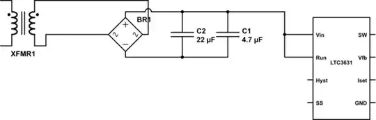
Local capacitors directly at Vin and Run going directly to the IC ground are essential. You could also consider adding reverse biased (negative clamping) diodes on these pins (to prevent them from somehow going below GND). A negative clamp diode at the SW node can be helpful too.

Adam Lawrence
  • 32,921
  • 3
  • 58
  • 110
1

There's an article by Morgan Jones in Linear Audio 5, where he shows that 1nF in series with 1k across the secondary is an amazingly generic solution to transformer ringing.

user207421
  • 881
  • 1
  • 8
  • 18
-1

You can use a Varistor in parallel with C1. Be sure to pick the Varistor with proper "Varistor Voltage" and surge ratings.

Suirnder
  • 200
  • 1
  • 4
  • 6
    Care to make the answer more helpful, rather than generic "use the right value of the right part" answers, please? – Anindo Ghosh Apr 05 '13 at 21:18