I have been thinking about how to produce an optocoupled input that works well over a wide voltage range, say 3V to 30V and I came up with the following schematic.
According to the simulator in CircuitLab it seems to work pretty well, maintaining an LED current between 5 and 10 mA and a total current of less than 20mA despite a tenfold change in input voltage.
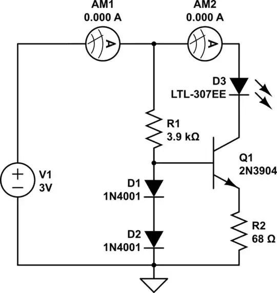
simulate this circuit – Schematic created using CircuitLab
(The ammeters shown are just to measure current. The LED represents the input LED of the optocoupler.)
Is this circuit a good idea, or is there some major problem I'm missing?
