0

I was trying to do a phase space for a Rossler circuit. I used python to approximate the solution and to do my own phase space. And I obtained this:enter image description here

It was for a Timstep equal to 0.00001 seconds and a TimeSTOP equal to 0.2 seconds. But when I uses the same parameters in LTspice it does not gave me the same thing and what's weird is when I change my Timestep to 0.000001 seconds LTspice tells me that my Timestep is to small or sometimes it actually shows me a phase space but I didn't change the parameters.

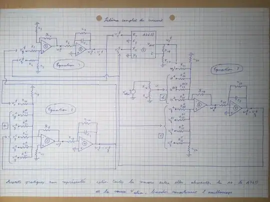
I believe that there is an error in my circuit. I'm using an TL082 OP-AMP (in the schematic it's named TL0820) and a AD633 Multiplier. Here's my schematic: enter image description here

At some blocks you can see multiple ressistor connected to the same earth. We are just using them if we want to pass from a chaotic behaviour to a periodic wone. In this case we just have to change which resistor is connected to earth.

Here's the value of all componentsenter image description here
Resistor with infinite values are implemented with open circuits.

And here's a written schematic :enter image description here
If someone could find a solution it would be very helpfull.

I tried to change de timestep and the timestop but it didn't help. I think that my error is somewhere in the circuit.

toolic
  • 5,637
  • 5
  • 20
  • 33
  • 1
    What are you actually doing with LTspice? It's not possible to set a timestep in LTspice; it uses a variable timestep and all you can do is set a *maximum* timestep. It's free to reduce the timestep as needed for fast transients. – Hearth Dec 07 '22 at 22:06
  • I want to reproduce the same phase space that I did in python. – Noah Dbc Dec 07 '22 at 22:16
  • 1
    You are using "," (comma) for a decimal point. Perhaps LTspice understands localization, but you may want to check the net list to be sure the comma is properly interpreted. Also, LTspice understands engineering units, thus, the value for C3 can be written as 10n instead of 0.00000001. – qrk Dec 07 '22 at 22:19
  • I changed what you said but the phase space is still incorrect – Noah Dbc Dec 07 '22 at 23:11
  • 1
    You might try adding some ESR to the capacitors, or select a fully modeled part from the database. – PStechPaul Dec 07 '22 at 23:29
  • What if you add a SPICE directive of `.options cshunt=1p` to your schematic? Also try using `UniversalOpamp2` before you attempt to use TI's TL082 PSpice model. – Ste Kulov Dec 07 '22 at 23:35
  • I did the change that you told me but I didn't change anything. One weird thing is that my X, Y and Z values are constant. – Noah Dbc Dec 08 '22 at 08:14
  • What do you mean by "the phase space is incorrect"? This is a classic example of a chaotic system; it's highly unlikely that two different simulations with different software would both result in the same output, as they'll make approximations in different places. – Hearth Dec 08 '22 at 16:31
  • Please [draw your schematic in a readable fashion](https://electronics.stackexchange.com/questions/28251/rules-and-guidelines-for-drawing-good-schematics?r=Saves_AllUserSaves). And you may want to use either `uic` or `startup`, or maybe just some `ic=<...>` to some capacitors, since these sort of chaoic circuits expect some sort of initial conditions. [For example this](https://electronics.stackexchange.com/a/532785/95619). – a concerned citizen Dec 09 '22 at 10:12

0 Answers0