15

I want to run a micro-controller from a 1S lipo through a 3V linear regulator. I need to measure the battery voltage however. The problem with using a voltage divider is that it would drain the battery over time which may or may not have protection circuitry built in. Since the AVR I'm using has a recommended input impedance of no higher than 10K I can't make the divider too large either.

Can anyone suggest a solution that would allow me to monitor this voltage without killing an unprotected battery over a couple of months? The circuit might enter deep sleep mode for an extended period meaning a voltage divider solution would consume the most power.


I ended up using both Hanno and Andy's solution. Thanks for all the input. Can only choose one answer unfortunately.

s3c
  • 2,525
  • 2
  • 21
  • 31

3 Answers3

22

The voltage divider needs to join the MCU in deep-sleep mode then... This can be achieved with a P channel FET (for instance).... When the MCU wakes up, it will want to measure the battery voltage so what it can do is turn on a circuit formed around a P channel FET that connects the battery +V to the voltage divider: -

enter image description here

The ADC input is shown to the right and there will be no voltage reaching it unless the MCU has activated the BC547 via the 10k resistor. Without activation, the P channel FET is turned off and virtually open circuit. If you can program the MCU to have a pull-down on its control pin when asleep that should be it, else add another (say) 10k resistor from that point to ground - this ensures the P channel FET is completely off.

A small word of warning, choose a P channel fet with low leakage current when off else there will be a slight drain on battery life but most fets are going to be under 100nA and many in the region of 1nA.

One final thing - how does the voltage regulator perform on it's standby current when the micro is off - do you need to take care of it as well?

Andy aka
  • 434,556
  • 28
  • 351
  • 777
  • 1
    I'm using the MCP1802 which has 25uA Q current, this part works fine. Thanks for the suggestion, exactly the type of solution I was looking for. – s3c Apr 05 '13 at 11:29
  • why would you use a P-Chan with transitor and not a single N-Channel fet? – jme Dec 06 '13 at 02:40
  • 1
    @jme - the ADC and MCU is referenced to ground and so it makes sense to switch the higher voltage feed. If I used an N channel device there would still be a drain permanently through the top resistor and thru the parasitic diodes in the MCU when it is in sleep mode. – Andy aka Dec 06 '13 at 11:12
  • @Andyaka what id the N-Fet was reversed so that the diode was reversed to not allow the current to flow to the ADC resistors? – jme Dec 09 '13 at 01:02
  • @jme - why don't you raise this as a proper question? – Andy aka Dec 09 '13 at 08:23
  • @Andyaka i guess i can, but i just don't feel it needs it. i just wanted to ask for clarification on design choice and think that it is relevant to the answer you have provided. – jme Dec 11 '13 at 22:51
  • It's a P channel FET btw – Andy aka Dec 12 '13 at 08:14
  • 3
    @jme "Why not use a low side switch (e.g. N-ch FET or μC i/o pin)?" is a good question. Here's why. The battery voltage can be greater than Vcc. When the low side switch is opened, then the battery voltage will appear on the A/D pin. That could lead to the burnage of the A/D, or to a leakage of the battery through the protection diodes on the A/D pin. [Related thread.](http://www.ccsinfo.com/forum/viewtopic.php?t=24210) – Nick Alexeev Sep 04 '14 at 01:42
  • 1
    Shouldn't you add a pull-down resistor on the base of the BC547? Otherwise, if the MCU is shut-off, that pin may float and occasionally enable the circuit and drain the battery. – Cerin Oct 11 '15 at 18:08
  • 1
    It's battery powered and if the op chooses to float or tristate that output then a resistor should be added. – Andy aka Oct 11 '15 at 18:39
  • I wander - what implications would be if I used a mosfet instead of BJT in this circuit? Leakage current of mosfet? – miceuz Oct 11 '16 at 15:00
  • Leakage current of mosfet receiving the logic signal shouldn't be a problem @miceuz – Andy aka Oct 12 '16 at 01:16
  • Would it be possible to build the circuit without the MOSFET, and connect the voltage divider immediately between the battery and the collector of the BC547? I guess this would come at the cost of a small error in the voltage read-out, that maybe could even be calculated? – dloeckx Dec 30 '21 at 01:02
  • @dloeckx sure it's possible to build that but when the BJT is "off", what will the voltage on the MCU pin be? – Andy aka Dec 30 '21 at 05:01
  • @Andyaka I'll keep the pin low with the MCU. I plan on adding this scheme to an ESP32, that can keep it's IO pin status even when in deep sleep mode. – dloeckx Jan 02 '22 at 16:38
  • @dloeckx I think you are missing the point of this Q and A. It's all about keeping power consumption really low when the PFET is inactivated. What you propose might just as well be done with the potential divider connected directly across the battery. Might I suggest you raise this as a new question because this isn't the place for extended discussions on a Q and A session that is terminated. – Andy aka Jan 02 '22 at 16:55
3

When you need to find out only when the battery is going to be dead (or give a warning shortly before that), you don't need to measure the its voltage directly. The output voltage of the regulator will fall below 3V before the battery reaches its minimum voltage. So you could measure the supply voltage of the micro controller.

Depending on its actual capabilities, you can do that without using a voltage divider. For an example, look the the ADC datasheet for a PIC12F1822, (on page 141): ADC block diagram

The PIC has an internal voltage reference, and can measure its value (the 'FVR buffer' which goes into the multiplexer). But it can also use the supply voltage as reference for ADC measurements (the ADPREF selector on the top).

Given that, one can simply measure the voltage reference with respect to the supply voltage, and get the supply voltage as an result. In the case of the 12F1822, the internal reference is 2.048V, and the ADC has 10 bit resolution. So when the supply voltage drops below 3.0V, the ADC result goes higher than 699:

$$ADCresult=1024*\frac{V_{in}}{V_{ref}}$$ which in our case is $$ADCresult=1024*\frac{2.048V}{V_{supply}}$$

Note that lower supply voltage means higher ADC results, since input voltage and reference voltage are swapped to the usual way. You can convert this formula to find out the actual supply voltage, given the ADC result.

hli
  • 2,336
  • 15
  • 17
1

Do you really need the linear regulator? Running the µC at full battery voltage will make things a lot easier. Besides, the regulator and the µC will always consume power, even in power-save modes, continuously draining the battery. Have a look at the data sheets and keep that in mind.

Because the ADC input (of a common sample-and-hold ADC, like that in an AVR µC) will only sink current when actually sampling a value, the transient low input impedance can be compensated for by simply adding a capacitor:

schematic

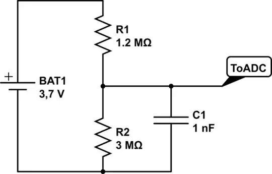
simulate this circuit – Schematic created using CircuitLab

The maximum sampling frequency will of course be limited this way since the capacitor will need time to re-charge through the large resistor before the next sampling is done, but I assume you will not be measuring more than, say, once a second anyway.

The time required to re-charge the capacitor can be set by varying its capacity and/or R1. Larger R1 = less "loss" of energy + lower max. sampling frequency. Smaller capacity will be charged quicker for a given resistor and so on.
You will want to maximize R1's value, and may then need to minimize the value of C1 to achive the desired sampling frequency.

The minimum capacity depends on the amount of charge the ADC will draw for a sample, which in turn is determined by the capacity of the ADC's sample buffer. For AVR devices I seem to remember that this value is specified in the datasheet. For other µCs I cannot tell, but the 1µF in the diagram will probably be more than enough in any case, and can possibly be reduced by a factor of 10 or so. The ADC's specs will tell.

Edit:

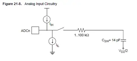
I found this in Atmel's datasheet for the ATmega1284p. The S&H buffer's capacitor is specified to 14 pico-farads, so a couple of nano-farads for C1 should be plenty.

Analog input circuitry from the ATmega1284p datasheet

See for instance the discussion here.

JimmyB
  • 3,823
  • 2
  • 18
  • 21
  • 1
    The linear regulator will be in turn be controlled by a ultra low current voltage detector, effectively removing both the uC and the regulator from the circuit should the battery drain below a certain value. – s3c Apr 05 '13 at 11:24
  • Ok, but is the regulator required for the µC supply, or can the µC be powered directly by Vbat, in which case it may work without any voltage divider. – JimmyB Apr 05 '13 at 13:04
  • 1
    I seem to understand now that you're not actually asking how the device can be built to use minimum power, but rather only how to make sure the LiPo is not destroyed. Is this correct? – JimmyB Apr 05 '13 at 13:07
  • 1
    Yes, the regulator is required for the uC supply. Using minimal power is preferred but not my main concern. – s3c Apr 05 '13 at 13:16
  • What does the output of the voltage detector you mentioned look like? – JimmyB Apr 05 '13 at 13:17
  • I'm using the MCP112, it's a push-pull voltage detector. (Voltage regulator is the MCP1802) – s3c Apr 05 '13 at 13:19
  • 1
    Possibly, you could put the voltage divider at its output then; but Andy Aka's proposal is probably the better way to go. – JimmyB Apr 05 '13 at 13:23
  • 1
    FYI, For the STM32L family, the ADC input impedence is 50K, so a voltage divider with megohm resistors is not going to work. – Mark Lakata Sep 11 '13 at 18:03