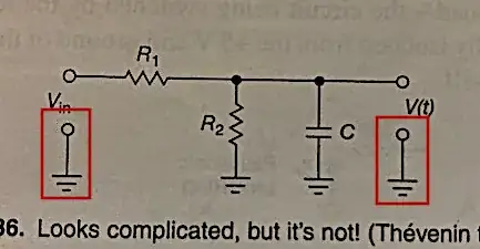
What does the schematic element highlighted in the following circuit fragments mean? Is it related to showing an open circuit?
3 Answers
These are actually multiple circuit elements that are connected together: A connection point (the non-filled circle) and a ground symbol. It means that you can connect something to this point in the circuit, and that point is in turn connected to the circuit's ground.
The connection points are shown explicitly to make it clear what the inputs and outputs of the circuit are.
- 14,865
- 28
- 50
-
Most circuit fragments are shown without connection points (or terminals). Are they shown in these fragments for a special reason? – Tim Cerka Dec 01 '22 at 21:12
-
1Yes, they're shown to make it clear where to apply the input voltage and where to take the output signal from. – Jonathan S. Dec 01 '22 at 22:30
Those things just emphasize that the input has two terminals (signal and ground), and the output likewise has two terminals (also signal and ground).
They are often omitted in textbook sample circuits, leaving the student to assume that the input and output have Ground connections.
- 57,014
- 1
- 48
- 127
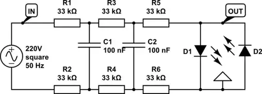
The circle is regarded as an input or output terminal and, the other symbol involved is regarded as ground or 0 volts: -
Image from here
- 434,556
- 28
- 351
- 777
-
I often use the circle symbol for a test point or a terminal, such as a binding post or banana jack. I use a reference designation of "TP" or "J" for these, but for a solder terminal I use "E", although it is not in the Wikipedia list. https://en.wikipedia.org/wiki/Reference_designator. It is discussed here: https://electronics.stackexchange.com/questions/572963/pcb-logic-board-reference-designator-e – PStechPaul Dec 01 '22 at 22:33


