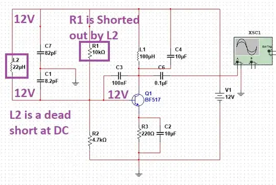
I have worked out an LC-based Colpitts Oscillator (sharing the schematics) that produces output which grows painfully slow from 10 pV to 500 mV in more than to 3 minutes and settles there. Despite banging my head loads, I have been unable to solve the issue. Any help shall be greatly appreciated. By the way, the oscillations have frequency of 3.5 MHz.
Asked
Active
Viewed 76 times
0
-
A picture of the output might be nice – Voltage Spike Dec 01 '22 at 14:49
-
Try decreasing R3 to increase Q1's transconductance. – Jonathan S. Dec 01 '22 at 14:53
-
3 minutes wall clock time, or 180 seconds on the simulation t axis? Does it spend most of that time at pV level and then finally get big, or does it rise linearly or exponentially? Try giving one of the capacitors an initial condition of voltage, the .ic directive, to give it an initial kick. Try altering a component that defines the loop gain, like almost all of them, and see if that variation stops it oscillating at all or gets it to start more quickly. – Neil_UK Dec 01 '22 at 14:53
-
Yes sir it's literally clock time – Awais Mushtaq Dec 01 '22 at 15:16
-
No sir, it spends almost equal tone in pV and nV ranges and eventually settles around 500 mV – Awais Mushtaq Dec 01 '22 at 15:20
-
I'll add the output stills to make it clear a bit – Awais Mushtaq Dec 01 '22 at 15:21
3 Answers
3
Your schematic shows a direct connection of 12 Volts to the base of the transistor through L2. There should be a capacitor in there somewhere.
Brevor
- 51
- 1
1
Andy aka
- 434,556
- 28
- 351
- 777
-
Ah! Thank you sir. I must be a dumb doing that. I'll shift it in BE loop n see if it helps – Awais Mushtaq Dec 01 '22 at 15:19
1
Besides what others have already said, C4 makes L1 pointless.
L1 is an RF choke that presents a high impedance at RF at the collector. C4 is a relatively high value capacitor that will be a low impedance at RF.
Since the gain is the roughly the ratio of the impedance in the collector circuit to the impedance in the emitter circuit, lowering the impedance at the collector will lower the gain, basically, C4 shorts out your RF signal.
What we would expect to see here is either no capacitor, or a small value capacitor(pico or nano Farads) that is resonant with L1 at the frequency of interest.
GodJihyo
- 17,628
- 1
- 16
- 45
-
Greatly appreciated. Thanks. I'm in learning phase so I thank you all. – Awais Mushtaq Dec 01 '22 at 16:13

