I'm trying to measure the speed of a small DC motor using a rotary encoder and an OPTO sensor, and counter input on myDAQ.
Here's my circuit on the breadboard:
The collector pin of the transistor is connected to the DIO1 port of the myDAQ.
And here's the LabVIEW code:
On the front panel, I only have the RPM numeric indicator.
When I run the program, with the rotary encoder spinning in the gap of the OPTO coupler, nothing happens. The RPM numeric indicator keeps showing 0.
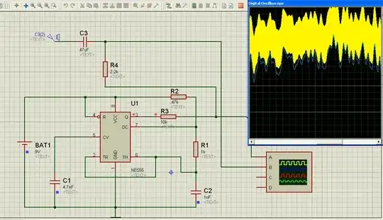
I thought the problem was my OPTO coupler. I tested it through analog input and I successfully visualised the pulses, as shown here:
So the problem is not the OPTO coupler.
And I can't seem to figure out the source of the problem. I would really appreciate some help please.
