3

I've developed an 8-bit computer, in the same vein as Ben Eater's wonderful 8-bit computer series. It's based on a collection of 74HCxx-series ICs, and fits (in theory!) on a single PCB board. I'm currently analyzing power supply requirements, and suspect 5 V, 2 A might not be enough.

My components, and their peak current draws, are roughly:

  • 10x 74HC04 (Not gate): 20 mA
  • 49x 74HC08 (And gate): 20 mA
  • 18x 74HC32 (Or gate): 20 mA
  • 29x 74HC86 (Xor gate): 20 mA
  • 12x 74HC157 (2x nibble multiplexer): 20 mA
  • 9x 74HC273 (8-bit Register): 20 mA
  • 4x 62256 (32-kilobyte RAM): 70 mA
  • ~50 green LEDs: 20 mA
  • Handful of others

Back of napkin math suggests max. ~4 A, but this feels very high. Based on number of components, what would be a reasonable power supply for such a circuit?
Michael Karas
  • 56,889
  • 3
  • 70
  • 138
mmap32
  • 31
  • 2
  • 1
    HC is not TTL type but CMOS type. Each logic gate would surely not consume 20mA unless you put 20mA worth of load on it. If all your LEDs are on, it would already consume 1A. And it would be sufficient to run them at some bright enough current, instead of forcibly at the rated 20mA. – Justme Nov 27 '22 at 00:37
  • 1
    20W: you can get that in a wall-wart, but 74HC will have different power draw depending on how high the clock speed is. – Jasen Слава Україні Nov 27 '22 at 00:43
  • 1
    You can definitely save some current on the LEDs. Most cheap LEDs are perfectly visible with 5 mA through them (you may find that 20 mA is too bright, even), and I've even used one for a power-sensitive application before that's visibly on with less than 0.5 mA. – Hearth Nov 27 '22 at 00:46
  • 2
    @Hearth I've used the *high efficiency* LEDs (2 mA) at 500 uA and they are (to me) just fine. I like them. Pricier, though, back when I was considering them more. – jonk Nov 27 '22 at 01:26
  • mmap32 - Hi, Just to help make sure that your calculations are accurate, where did you see 20 mA as the power consumption of a 74HC04 (for example)? That doesn't match the [TI SN74HC04 datasheet](https://www.ti.com/lit/ds/symlink/sn74hc04.pdf) nor the [Diodes Inc 74HC04 datasheet](https://www.diodes.com/assets/Datasheets/74HC04.pdf) (just to give 2 examples). I wonder if you have misinterpreted the clamp current in the absolute maximum rating section (which is shown as +/- 20 mA) and used that? Anyway, please [edit] your question to explain your figures. Thanks. – SamGibson Nov 27 '22 at 01:37
  • 2
    As SamGibson suggests, these numbers doesnt make sense at all. The 74HC08 draws a maximum of **20uA**. Same as the '04. You are a factor of 1000 off... – Linkyyy Nov 27 '22 at 18:52
  • Thank you all for the help! Indeed @SamGibson is right - I misread the spec sheets, yet am struggling to understand the terminology. Is input current the value I'm looking for to compute the average current draw? The TI PDF cites input leakage current as +/- 1 µA – mmap32 Nov 30 '22 at 15:49
  • @mmap32 No, input leakage current is max -/+ 1 uA ever in worst conditions. Even if you had 1000 inputs, the leakage would be max 1 mA. CMOS inputs take virtually no static current so it can be ignored in your simple case. However each gate will consume a surge of current when it changes state, some datasheets have formulas how to approximate current consumption when you have a chip with input toggling at some frequency. – Justme Nov 30 '22 at 19:04

3 Answers3

6

Are you really running the LEDs at 20mA?

Most modern LEDs when used as indicators only need 1-2 mA to be adequately bright. I usually use a 1k or 2.2k resistor for the LEDs when driving them from 5V rather than the 220 ohm as in the linked reference.

The LEDs will probably be the dominant consumption and if you run them at 2mA each that is a total of 100mA when all lit.

CMOS logic consumes sub-microamp supply current at room temperature when idle and only a very short burst of current when actually switching. Most of the logic at any moment will not be changing state so will consume very little current.

What frequency are you running the logic at?

The power consumption of CMOS logic increases proportionally with frequency of operation.

The link you reference only uses a few hundred Hertz for the clock in which case the total logic consumption will be very low, maybe only a milliamp or two.

I expect the power supply you already have will be more than adequate.

Do ensure that you have adequate decoupling for all devices - the surge of current can cause problems because of the inductance of the power wiring.

Kevin White
  • 32,097
  • 1
  • 47
  • 74
5

Chances are that your current is going to be overwhelmingly dominated by the LED currents. Those CMOS parts draw almost no static current, and a dynamic current will only come into play if you have many MHz clock frequency. As others have said, I would suggest much lower LED currents. Try and see what is acceptable, but 1-3mA is probably more than adequate. So use appropriate resistors to get that current. I would be very comfortable with a vanilla 2A supply as used for a Raspberry Pi unless you insist on blindingly bright LEDs (and even then, that would leave a huge 1A for everything else, so you'd still be okay).

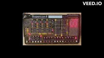
Here is an emulated 4-bit microcomputer with visible registers, PC, ALU and a block of memory (a "badge" about 180mm x 90mm). It runs from 2 AA batteries drawing about 20mA average total as shown! The LEDs are not crazy bright in an office setting, but are very visible in somewhat subdued light.

enter image description here

Spehro Pefhany
  • 376,485
  • 21
  • 320
  • 842
4

4A at 5V is 20W: you can get that in a wall-wart.

But 74HC will have different power draw depending on how high the clock speed is. If 2A is not enough, just reduce the clock speed until it is.