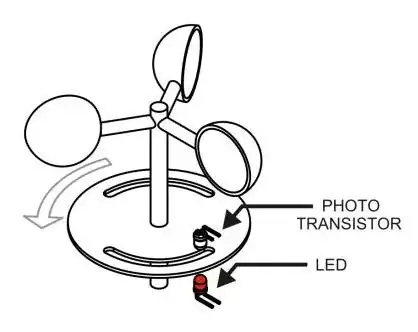
There is some confusion here so I looked at the picture linked to by the OP(below)
If the duty period of "something" is 3us then it just can't be caused by the gaps in the spinning wheel - it has to be that the led is pulsing as a means of providing a counter-measure to normal sunlight getting in. That's the only explanation I can think of.
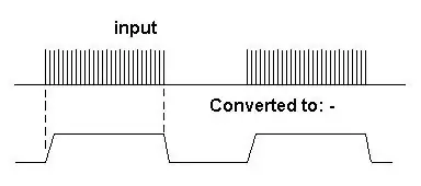
Given also the assumption that the LED is driven with an asymmetrical duty cycle up to possibly 100 times the mark period, it might be feasible to construct a circuit that converts the pulse trains into a positive voltage and when the opto is "shut" it returns 0V. Maybe something like this: -
Therefore I would (given all the assumptions and reading between the lines) propose that the photodiode in the opto-coupler is buffered with a transimpedance amp and then its output feeds a conventional AM detector built around a diode, resistor and capacitor. This output then feeds a comparator/data slicer and is then suitable for an Arduino input
To make things less hardware intensive on the analogue side the pulse train from the transimpedance amp could directly feed an Arduino input and the software can "construct" a demodulated version which can be counted.
The counter would be two pulses per rev (assuming the picture is representative) and this should translate to wind-speed. I say "should" because there is likely to be a non-linear relationship between wind-speed and rotational speed. Good luck with this project.